Summary
The new feature, Optimization in RADIOSS, makes it easy to set up an optimization problem in RADIOSS Block Format. A typical optimization problem has three elements:
| • | Objective (minimize mass of the structure) |
| • | Constraints (stress less than 200 MPa and maximum displacement less than 10mm) |
| • | Design variables (parameters that can be adjusted to improve the design) |
The setup of optimization in RADIOSS requires an extra input file apart from the usual Starter and Engine input files. The required file is an optimization input file named <name>.radopt (the Starter and Engine files are named <name>_0000.rad and <name>_0001.rad, respectively). The <name>.radopt file defines optimization entities such as the optimization objective, optimization constraints, design variables, optimization responses and so on.
For more RADIOSS optimization details, refer to Design Optimization in the User’s Guide.
Title
Optimization in RADIOSS for B-Pillar (Thickness optimization)
|
|
Number
51
|
Brief Description
This example defines a crash test on B-Pillar. The optimization objective is to minimize the mass of the B-Pillar by changing the shell thickness. The intrusion, which is defined by the optimization constraint is required to not be larger than the original model, to keep the passenger safe.
|
RADIOSS Optimization Keywords
| • | Optimization design variable (/DESVAR) |
| • | Relate design variables to analysis model properties (/DVPREL1) |
| • | Optimization design response (/DRESP1) |
| • | Optimization design constraint (/DCONSTR) |
|
RADIOSS Options
|
Input File
Optimization in RADIOSS for B-Pillar (Thickness Optimization):
<install_directory>/demos/hwsolvers/radioss/51_optimization_bpillar
|
Technical / Theoretical Level
Advanced
|
Overview
Aim of the Problem
The purpose of this example is to show how to set up an optimization, based on a crash test (RADIOSS Block model).
Physical Problem Description
Cut the B-Pillar from the full car model and set the initial velocity in the rigid cylinder.
Units: mm, s, ton, N, and MPa
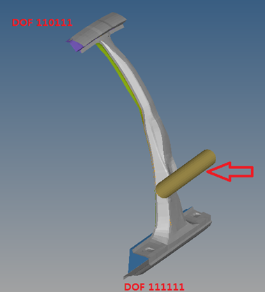
Optimization Problem
| • | Objective: Minimize mass |
| • | Constraint: Maximum displacement of node 2021524 in Y direction (inside reinforcement) < 19.7 [mm] |
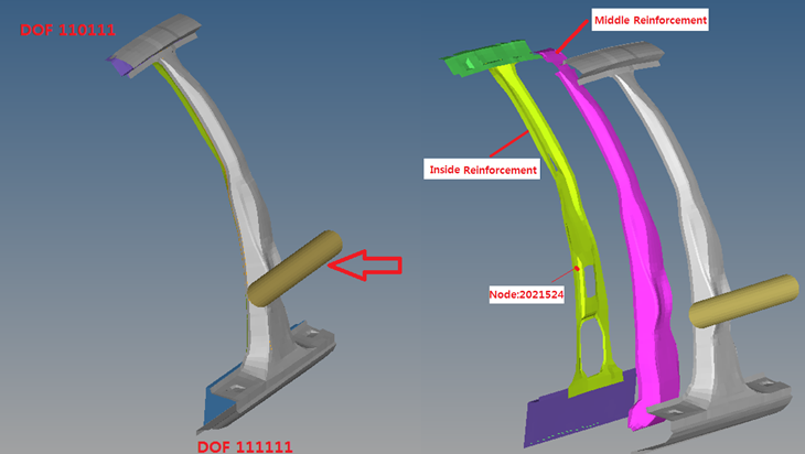
Fig 1: Problem description
| - | Shell thickness of the middle reinforcement - allowable range [0.5mm, 3.0mm] |
| - | Shell thickness of the inside reinforcement - allowable range [0.5mm, 3.0mm] |
Analysis, Assumptions and Modeling Description
Detailed Optimization Setup
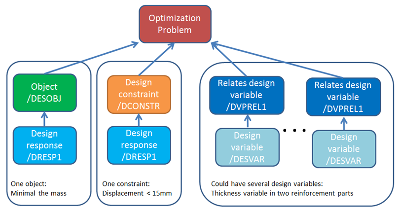
Fig 4: RADIOSS optimization setup
Optimization Objective
/DESOBJ is used to define optimization objective. In this example, it defines the minimal response #1.
Response #1 defines an optimization response that is the combination of mass in part group #2000329 (defined in the RADIOSS Starter file), which includes both parts of the middle reinforcement and the inside reinforcement.
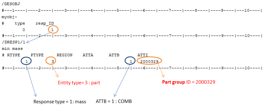
Fig 5: Optimization objective setup in RADIOSS optimization
Optimization Constraint
In this example, you want to constrain the intrusion to not be larger than the original model (before optimization). In the original model, max. y-displacement in node 2021524 is 19.7mm. Define this value as cmax in /DCONSTR and in response 2, define 19.7 as the max. y-displacement (with RTYPE=5, ATTA=7) in node 2021524 (with PTYPE=1, ATTI=2021524).
Depending on your own optimization criteria, the value in cmax may differ.
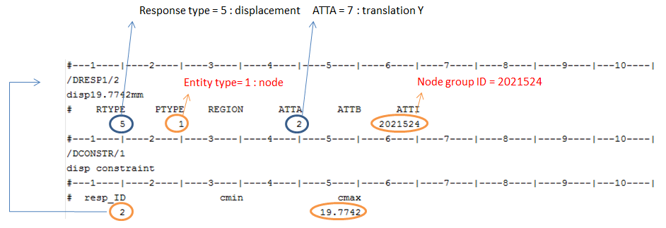
Fig 6: Optimization constraint setup in RADIOSS optimization
Design Variable
/DESVAR is used to define design variables and /DVPREL1 to relate design variables to analysis model property.
Two different design variables are defined: One for part 2000327 and one for part 2000329
For example, the design variable for inside reinforcement (part 2000327) is defined:
| • | In /DESVAR with the range [0.5,3.0] - this will be used in /DVPREL1. |
In /DVPREL1 with prop_typ and prop_fid the above variable can be used for shell thickness, and with prop_ID the thickness in shell property 2000327 will be used in the optimization run.
| • | COEF_1 in /DVPREL1. In each iteration, Pi (the thickness value) will be equal to C0+(1.0*X), where  which is defined in /DESVAR. which is defined in /DESVAR. |
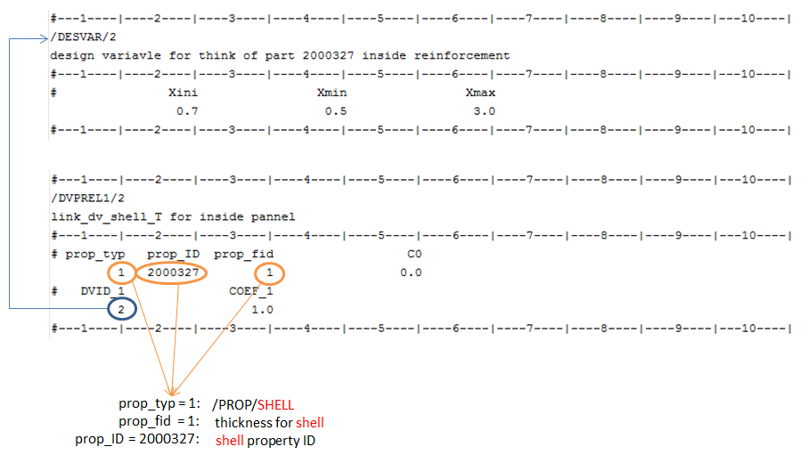
Fig 7: Design variable setup in RADIOSS optimization
RADIOSS Options Used
/INIVEL and /INTER/TYPE7 are also used.
Use /INIVEL to optimize the B-Pillar under same initial kinetic energy.
In this example, you want to change the shell thickness to have minimal mass of B-Pillar. There is initial penetration, due to thickness changes between two contact parts. Defining initial thickness in /PART can avoid this issue and the thickness is only used to calculate the gap in interfaces.
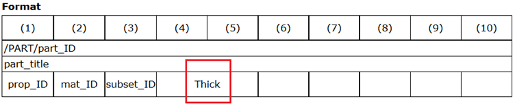
Fig 8: /PART card in RADIOSS Starter file
Simulation Results and Conclusions
In the results check the following:
| 1. | The latest design provides the best results. Verify whether the result is feasible or not. In the *.out file (Neon-b_pillar.out) this data is at end of each iteration. |
“FEASIBLE DESIGN (ALL CONSTRAINTS SATISFIED).“ - indicates that the design is good.
“INFEASIBLE DESIGN (AT LEAST ONE CONSTRAINT VIOLATED).” - indicates that the design variable definition needs to be checked/improved.
This information can also be found in the output file hwsolver.mesg.
| 2. | In the *.out file (Neon-b_pillar.out), check/verify the optimization definition. “Objective Function: Minimize Combined Mass”, “Run Type: Sizing Optimization” and so on. |
| 3. | By running the Optimization in RADIOSS, an equivalent OptiStruct model will also be automatically created and named *.fem (Neon-b_pillar.fem). |
Check the results in the *.eslout (Neon-b_pillar.eslout), in the *h3d file, or in each ANIM, T01 file. The *.eslout file contains the value of optimized objective in each iterations.

Fig 9: Optimized results in each iterations in *selout file
In the original model, the mass of the two parts is 3.0011e-3[Ton] and the optimized mass for these two parts is 2.4158e-3[Ton]. The mass is reduced by approximately 19.5%.
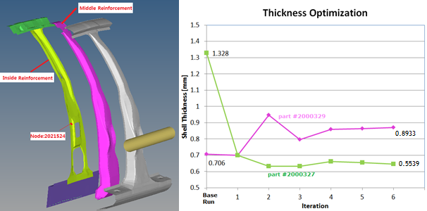
The thickness of part #2000327 is 1.328mm and the optimized thickness is 0.5539mm. The thickness is reduced.
The thickness of part #2000329 is 0.7060mm and the optimized thickness is 0.8933mm. The thickness in this model increased in order to get better performance of these two parts (in response 1, ATTB =1 (for COMB) is defined).
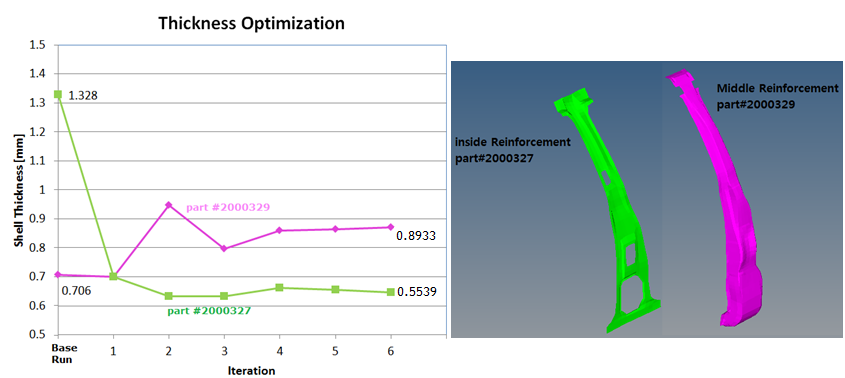
Fig 10: Optimized results of shell thickness of two reinforcement parts
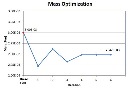
Fig 11: Optimized results of total mass of two reinforcement parts
In the last iteration, the mass was reduced to 2.4158e-3[Ton]. This new design still meets the constraint (< 19.7[mm]), defined in /DCONSTR.
In node 2021524, the max. y-displacement:
19.57[mm] (last iteration) < 19.7 [mm] (in constraint). Meets the constraint.
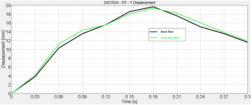
Fig 12: y-displacement on node 2021524 in original model and optimized model


