HyperWorks Solvers

/FAIL/LAD_DAMA

/FAIL/LAD_DAMA

Previous topic Next topic Expand/collapse all hidden text  

/FAIL/LAD_DAMA

Previous topic Next topic JavaScript is required for expanding text JavaScript is required for the print function  

Block Format Keyword

/FAIL/LAD_DAMA - Ladeveze Composite Failure Model

Description

Describes the Ladeveze failure model for delamination (interlaminar fracture). [1]

This failure model is available for orthotropic solids and thick shells and it is compatible with /MAT/LAW12, /MAT/LAW14 and /MAT/LAW25.

Format

(1)

(2)

(3)

(4)

(5)

(6)

(7)

(8)

(9)

(10)

/FAIL/LAD_DAMA/mat_ID/unit_ID

K1

K2

K3

Y0

Yc

k

a

symbol_tmax

Ifail_sh

Ifail_so


Optional line:

(1)

(2)

(3)

(4)

(5)

(6)

(7)

(8)

(9)

(10)

fail_ID


hmtoggle_plus1Flag Definition

Field

Contents

SI Unit Example

mat_ID

Material identifier

(Integer, maximum 10 digits)


unit_ID

Optional unit identifier

(Integer, maximum 10 digits)


K1

Interlaminar stiffness in direction 1

Default = 1030  (Real)

symbol_Pa_m

K2

Interlaminar stiffness in direction 2

Default = 1030  (Real)

symbol_Pa_m

K3

Interlaminar stiffness in direction 3

Default = 1030  (Real)

symbol_Pa_m

Coupling factor between delamination Mode I and Mode II

Default = 0  (Real)


Coupling factor between delamination Mode I and Mode III

Default = 0  (Real)


Y0

Yield energy damage for delamination start

Default = 1030  (Real)


Yc

Critical energy damage parameter for full delamination

Default = (Real)


k

Crack propagation velocity time constant

Default = 0  (Real)

fail_lad_SI_k

a

Crack propagation velocity multiplier

Default = 1030  (Real)


symbol_tmax

Dynamic time relaxation (Comment 3)

Default = 1030  (Real)

symbol_S_unit

Ifail_sh

Shell failure flag

Default = 1  (Integer)

= 1: Shell is deleted, if damage criterion is reached for one layer.

= 2: Shell is deleted, if damage criterion is reached for all shell layers.


Ifail_so

Solid failure flag

Default = 1  (Integer)

= 1: Solid is deleted, if damage criterion is reached for one integration point.

= 3: Out-of-plane stress is set to zero, if damage is reached for one integration point of solid ().


fail_ID

(Optional) Failure criteria identifier (Comment 2)

(Integer, maximum 10 digits)


hmtoggle_plus1Example (Composite)

#RADIOSS STARTER

/UNIT/1

unit for mat and failure

#              MUNIT               LUNIT               TUNIT

                   g                  mm                  ms

#---1----|----2----|----3----|----4----|----5----|----6----|----7----|----8----|----9----|---10----|

/MAT/COMPSH/1/1

composite example

#              RHO_I

             .001506

#                E11                 E22                NU12     Iform                           E33

              144000               10000                 .25         0                         20000

#                G12                 G23                 G31              EPS_f1              EPS_f2

                4200                4200                4200                   0                   0

#             EPS_t1              EPS_m1              EPS_t2              EPS_m2                dmax

                   0                   0                   0                   0                   0

#              Wpmax               Wpref      Ioff                         ratio

             1000000                   0         0                             0

#                  b                   n                fmax

                   0                   0             1000000

#            sig_1yt             sig_2yt             sig_1yc             sig_2yc               alpha

               10100               10100               10100               10100                   0

#           sig_12yc            sig_12yt                c_12          Eps_rate_0       ICC

               10068               10068                   0                   0         0

#          GAMMA_ini           GAMMA_max               d3max

                   0                   0                   0

#  Fsmooth                Fcut

         0                   0

/FAIL/LAD_DAMA/1/1

#                 K1                  K2                  K3              Gamma1              Gamma2

                2000                2000                2000               1E-20               1E-20

#                 Y0                  YC                   K                   A             Tau_max

                  40                 160              100000                   1                 .01

# Ifail_sh  Ifail_so

         1         3

#---1----|----2----|----3----|----4----|----5----|----6----|----7----|----8----|----9----|---10----|

#enddata

#---1----|----2----|----3----|----4----|----5----|----6----|----7----|----8----|----9----|---10----|

hmtoggle_plus1Comments
1.The Ladeveze failure damage model for delamination:

fail_lad-dama_delam1

fail_lad-dama_delam1A[2]

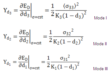
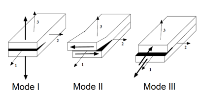
For Quad 2D element, only Mode II and Mode III are available.

Where, di is the internal damage parameters associated with its fracture mode.

The damage evolution law is controlled by equivalent damage energy release rate.

The evolution of the damage parameters is strongly coupled with coupling factor and . These two material parameters come from delamination tests.

For the present failure model, consider that d1 = d2 = d3 = d, with:

Where, d = 1

is a measure of the failure ductility, the lower the value the more ductile the failure.

is the minimum failure duration, for example, the increase of failure energy between Y0 and Yc cannot last for less than this value.

The function w(Y) is computed as:

If the damage parameter "d " < 1.0, the stressesare decreased according to the following function:

A relaxation technique is used by gradually decreasing the stress:

With,

where,

t is the time

tr is the start time of relaxation when the damage criteria is reached

symbol_tmax is the time of dynamic relaxation

is the stress components at the beginning of damage

2.The fail_ID is used with /STATE/BRICK/FAIL and /INIBRI/FAIL. There is no default value. If the line is blank, no value will be output for failure model variables in the /INIBRI/FAIL (written in .sta file with /STATE/BRICK/FAIL option).
3.The value of symbol_tmax determines a period of time after failure criterion is reached when the stress in failed element is gradually reduced to zero, then the element is deleted. This is necessary to avoid instability coming from a sudden element deletion and failure "chain reaction" in the neighboring elements. With this value, elements will not be deleted, even if the failure criterion is reached. Normal value of symbol_tmax is 10 times higher than the actual times step should be set in the card directly.
hmtoggle_plus1References

[1] O. Allix, P. Ladevèze, “Interlaminar interface modeling for the prediction of delamination”, Composite structure 22 (1992) 235-242.

[2] L. Gornet, “Finite Element Damage Prediction of Composite Structures”.