Model Element
|
Description
|
Format
|
Revolute Joint
<Force_JointFriction
id = “integer”
[ label = “string” ]
joint_id = “integer”
mu_static = “real”
mu_dynamic = “real”
[ max_stiction_deform = “real” ]
[ bristle_stiffness = “real” ]
[ damping_effects = “real” ]
[ viscous_effects = “real” ]
[ stiction_trans_vel = “real” ]
[ inactive = “None | Static” ]
[ effect = “All | Stiction | Sliding” ]
[ inputs = “4-bit integer” ]
[ torque_preload = “real” ]
[ friction_arm = “real” ]
[ bending_reaction_arm = “real” ]
[ pin_radius = “real” ]
/>
|
Spherical Joint
<Force_JointFriction
id = “integer”
[ label = “string” ]
joint_id = “integer”
mu_static = “real”
mu_dynamic = “real”
[ max_stiction_deform = “real” ]
[ bristle_stiffness = “real” ]
[ damping_effects = “real” ]
[ viscous_effects = “real” ]
[ stiction_trans_vel = “real” ]
[ inactive = “None | Static” ]
[ effect = “All | Stiction | Sliding” ]
[ inputs = “4-bit integer” ]
[ torque_preload = “real” ]
[ ball_radius = “real” ]
/>
|
Translational Joint
<Force_JointFriction
id = “integer”
[ label = “string” ]
joint_id = “integer”
mu_static = “real”
mu_dynamic = “real”
[ max_stiction_deform = “real” ]
[ bristle_stiffness = “real” ]
[ damping_effects = “real” ]
[ viscous_effects = “real” ]
[ stiction_trans_vel = “real” ]
[ inactive = “None | Static” ]
[ effect = “All | Stiction | Sliding” ]
[ inputs = “4-bit integer” ]
[ force_preload = “real” ]
[ reaction_arm = “real” ]
[ initial_overlap = “real” ]
[ overlap_delta = “Constant | Increase | Decrease” ]
/>
|
Cylindrical Joint
<Force_JointFriction
id = “integer”
[ label = “string” ]
joint_id = “integer”
mu_static = “real”
mu_dynamic = “real”
[ max_stiction_deform = “real” ]
[ bristle_stiffness = “real” ]
[ damping_effects = “real” ]
[ viscous_effects = “real” ]
[ stiction_trans_vel = “real” ]
[ inactive = “None | Static” ]
[ effect = “All | Stiction | Sliding” ]
[ inputs = “4-bit integer” ]
[ force_preload = “real” ]
[ torque_preload = “real” ]
[ pin_radius = “real” ]
[ initial_overlap = “real” ]
[ overlap_delta = “Constant | Increase | Decrease” ]
/>
|
Universal Joint
<Force_JointFriction
id = “integer”
[ label = “string” ]
joint_id = “integer”
mu_static = “real”
mu_dynamic = “real”
[ max_stiction_deform = “real” ]
[ bristle_stiffness = “real” ]
[ damping_effects = “real” ]
[ viscous_effects = “real” ]
[ stiction_trans_vel = “real” ]
[ inactive = “None | Static” ]
[ effect = “All | Stiction | Sliding” ]
[ inputs = “4-bit integer” ]
[ torque_preload = “real” ]
[ friction_arm = “real” ]
[ bending_reaction_arm = “real” ]
[ pin_radius = “real” ]
[ yoke_choice = “i_yoke | j_yoke” ]
/>
|
Attributes
|
id
|
Element identification number, (integer>0). This number is unique among all Force_JointFriction elements.
|
label
|
A string containing the element description.
|
joint_id
|
Specifies the joint ID of the joint where the friction force is applied.
|
mu_static
|
Specifies the static friction coefficient  in the joint. in the joint.
MU_STATIC > 0.
Default: NONE
|
mu_dynamic
|
Specifies the dynamic friction coefficient  in the joint. in the joint.
MU_DYNAMIC > 0.
Default: NONE
|
max_stiction_deform
|
Specifies the maximum deformation that can occur in a joint for static friction.
If specified to be non-zero, a finite static friction force is applied even if the relative velocity is zero.
Default = 0.01 length units
|
stiction_trans_vel
|
Real value of the absolute velocity below, which the friction transitions from dynamic friction to static friction.
Default = 0.1 length/time.
|
inactive
|
Specify “STATIC” to disable joint friction during static analysis.
Default: NONE
|
effect
|
Specifies the frictional effect. By default, both static and dynamic friction is considered. Stiction uses only static friction, sliding uses only dynamic friction.
Default: ALL
|
inputs
|
A 4-bit integer value specifies the input forces to the friction model. By default, all the preload and joint reaction forces are included. Valid values are 0 or 1 for each bit.
Default: 1111
There are four choices to be made:
| • | 4th bit: Torsional_Moment |
Setting a 0 or 1 for each bit of the inputs value controls individual inputs.
Thus:
| • | 1111 – All four inputs are included |
| • | 0000 – None of the four inputs are included |
| • | 1000 – Only include Preload |
| • | 1101 – Include Preload, Reaction_Force and Torsional_Moment, but not Bending_Moment |
| • | 1001 – Include Preload and Torsional_Moment, but not Reaction_Force and Bending_Moment |
Options available per joint type are as defined below:
| • | Translational - Preload, Reaction_Force, Bending_Moment, Torsional_Moment |
| • | Cylindrical, Revolute, Universal, Hooke - Preload, Reaction_Force, Bending_Moment |
| • | Spherical: Preload, Reaction_Force |
|
force_preload
|
Specifies the preload friction force for Translational and Cylindrical joints.
Default : 0.0 force units
|
torque_preload
|
Specifies the preload friction torque for Revolute, Cylindrical, Universal and Spherical joints.
Default: 0.0 force*length units
|
friction_arm
|
Specifies the moment arm used to compute axial friction torque in revolute, universal joints.
Default: 1.0 length units
|
reaction_arm
|
Specifies the moment arm of the reaction torque about the Translation joint axial axes.
Default: 1.0 length units
|
bending_reaction_arm
|
Specifies the moment arm to compute the bending moment in Revolute, Hooke and Universal joints.
Default: 1.0 length units
|
pin_radius
|
Specifies the radius of the pin for Revolute, Cylindrical, Hooke and Universal joints.
Default: 1.0 length units
|
ball_radius
|
Specifies the radius of the Spherical joint.
Default: 1.0 length units
|
initial_overlap
|
Specifies the initial overlap of the sliding parts in Translation and Cylindrical joints.
Default: 1000.0 length units
|
overlap_delta
|
Specifies friction characteristics in the sliding joint.
INCREASE – Overlap increases as the I Marker translates in the positive direction of the z-axis of the J Marker.
DECREASE – Overlap decreases in the positive direction of the J marker.
Default: CONSTANT
|
yoke_choice
|
Specifies the yoke choice for Hooke and Universal joints.
|
bristle_stiffness
|
Specifies the bristle stiffness in the LuGre model,  . See Comments 1-4 for more information. . See Comments 1-4 for more information.
Default: 100
|
damping_effects
|
Defines the damping coefficient for the pre-displacement (or stiction) regime. Its main role is to damp out bristle vibrations in the pre-displacement regime. Represented as  in this documents. See Comments 1-4 for more information. in this documents. See Comments 1-4 for more information.
Default: 0.316
|
viscous_effects
|
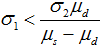
Specifies the coefficient for the viscous damping force that occurs when relative sliding actually begins. Represented as  in this document. See Comments 1-4 for more information. In order to guarantee passivity of the LuGre model (for example, it always dissipates energy) the following condition must be met: in this document. See Comments 1-4 for more information. In order to guarantee passivity of the LuGre model (for example, it always dissipates energy) the following condition must be met:
Default: 0.0004
|
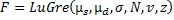
| 1. | MotionSolve uses the LuGre (Lundt-Grenoble) model for friction. This model may be summarized as follows: |
A bristle model is used to idealize friction. Friction is modeled as the average deflection force of elastic springs between two mating surfaces. When a tangential motion is applied, the bristles will deflect like springs. If the deflection is sufficiently large, the bristles start to slip. The slip velocity between the mating surfaces, vslip, determines the average bristle deflection for a steady state motion. It is lower at low velocities, which implies that the steady state deflection decreases with increasing velocity. Figure 1 below depicts the bristle model.
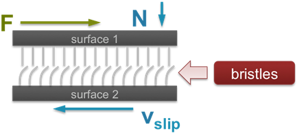
Figure 1: The bristle model for friction
|
| 2. | The LuGre model is capable of representing several different effects: |
| • | The effect of the mating surfaces being pushed apart by lubricant. |
| • | The Stribeck effect (at very low speed). When partial fluid lubrication exists, contact between the surfaces decreases and thus friction decreases exponentially from stiction. |
| • | Rate dependent friction phenomena, such as varying break-away force and frictional lag Static friction between two surfaces. |
|
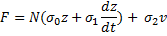
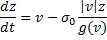
| 3. | The LuGre model, for friction in one dimension, is expressed as follows: |

|
States
z = bristle deflection
Inputs
v = slip velocity
vs = static > dynamic friction transition slip velocity
Parameters
s0 = bristle stiffness
s1 = damping coefficient
s2 = viscosity coefficient
vs = stiction transition velocity
Outputs
F = friction force
|
|
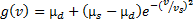
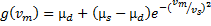
| 4. | The LuGre function may be explained as follows: the function  defines the shape of the friction function. defines the shape of the friction function. |
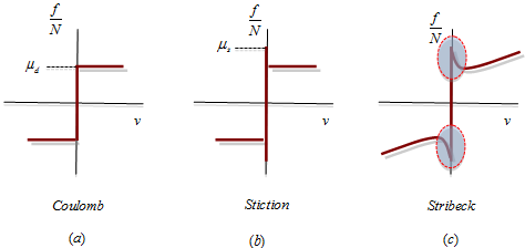
Figure 2: The three characteristics of a friction function
As shown in Figure 2 above, can model Coulomb friction 2(a), Stiction 2(b), and the Stribeck effect (2c). From its definition:  .. ..
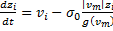
At the microscopic level, two surfaces make contact at various asperities. These asperities are represented with bristles, and the bristles deflect like a spring when there is a relative velocity between the two surfaces. The deflection of the springs gives rise to the friction force. If the deflection is sufficiently large, then the bristles will slip in a highly random manner because of the irregular surfaces. Although the deflection of the bristles is random, the LuGre model only considers the average deflection. The average deflection of the bristles,  , is modeled by a first-order differential equation that relates bristle deflection to slip velocity, coefficients of friction, and normal force. , is modeled by a first-order differential equation that relates bristle deflection to slip velocity, coefficients of friction, and normal force.
| • | The parameter represents the bristle stiffness, and it models the stiffness resisting micro-deformation in the friction element. |
| • | The parameter represents the damping in the pre-displacement (or stiction) regime. When the friction state is far away from this regime, its influence is negligible since  tends to zero on a faster time-scale than the slip velocity, tends to zero on a faster time-scale than the slip velocity, , as the system leaves the pre-displacement zone where the velocity , is close to zero. , as the system leaves the pre-displacement zone where the velocity , is close to zero. |
| • | The parameter represents viscous damping. This is primarily responsible for the increase in friction force with the increase in the slip velocity,. The viscous effect dominates the damping when there is a slip velocity between the two surfaces. |
|
| 5. | The LuGre model can capture hysteresis as shown in Figure 3 below. |
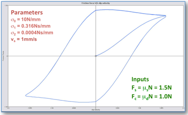
Figure 3: Hysteresis in the LuGre friction model
|
| 6. | The LuGre model also captures frequency dependent hysteresis as shown in Figure 4 below. |
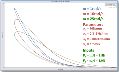
Figure 4: Rate dependent hysteresis in the LuGre friction model
|
| 7. | The LuGre model can also be used to describe friction in N -Dimension as follows: Let the 3-D space of relevance. |
| • | Slip velocity 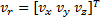 , ,  |
| • | Bristle states  , , |
Now define the following terms:
| • |  |
The 3-D LuGre friction model is defined by the equations below:
| • |  |
| • | 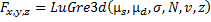 , ,  |
| • |  |
|
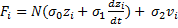
| 8. | Friction force coupling. |
The coupling effect leads to the familiar friction ellipse that defines the limiting forces when sliding is seen in x, y, z directions, as shown in Figure 5 below.
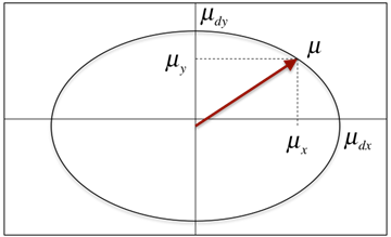
Figure 5: The LuGre2D model supports the concept of a friction ellipse.
|
| 9. | Friction in a Revolute joint. |
Figure 6 below describes the geometry of a Revolute joint. A circular pin, shown in grey, holds two bodies (labeled 1 and 2) so that they are able to rotate about the z-axis, which is normal to the plane of the picture. The inset shows a y-z section of the joint cutting through the pin.
Figure 6: The geometry for a revolute joint
The following geometrical properties are important for friction calculations:
| • | The radius of the pin, denoted as rp. |
| • | The bending reaction arm, rb. The width of the inside part, Part-1, is 2*rb. |
| • | The friction arm, rn. This is the effective radius at which the axial force acts. |
In a multi-body simulation, a joint can be loaded in several ways, thus generating reactions forces and torques. Each of these contributes to the interface dynamics by means of friction forces. For a revolute joint, there are four contributing effects:
| • | Friction on the cylindrical surface of the pin, caused by the normal force in the xy plane, Nxy. |
| • | Friction on the end-caps of the pin, caused by the axial force, Nz. |
| • | Friction caused by the force couple equivalent to the moment arm in the xy plane, Nrxy. |
| • | Friction caused by the assembly preload in the joint. |
The calculation of each of these effects is explained next.
Friction on the cylindrical surface of the pin, caused by the normal force in the xy plane, Nxy
Figure 7(a) describes the contribution coming from the loading in the x-y plane. The contact surface is at the pin and hence the slip velocity depends on the pin radius and joint relative angular velocity  . .
The slip velocity in the x-y plane is =  . .
The force normal to the pin surface, 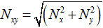 . .
The friction force is: . .
The torque generated by this friction force will be:  ;. ;.
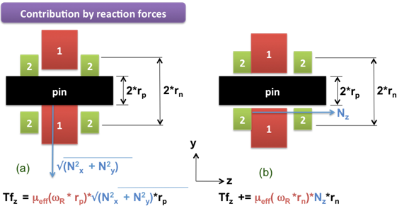
Figure 7: Friction forces caused by the reaction forces
Friction on the end-caps of the pin, caused by the axial force, Nz
From Figure 7(b) we see that friction due to axial loading leads to an annular disc-like contact surface with an effective radius of rn. The slip velocity in the axial direction is therefore:  . The force normal to the pin surface is . The force normal to the pin surface is  . .
The friction force magnitude to axial loading is  . .
The friction torque due to axial loading is  . .
Friction caused by the force couple equivalent to the moment arm in the xy plane, Nrxy
The reaction moments can introduce additional frictional torque. This is shown in Figure 8 below.
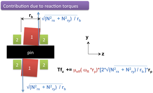
Figure 8: Friction forces caused by the reaction moments
In this case, we need to first identify the individual reactions obtained from the reaction torques. Based on Figure 6, it is seen that since the moment arm of the reaction moment is rb, the equivalent force in the couple would be:
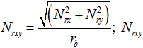 is the reaction force acting on the contact surface. is the reaction force acting on the contact surface.
The normal force acts at a radius rp. Hence, the friction force can be expressed as:
 . .
The frictional torque caused by this friction force is  . .
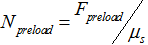
Friction caused by the assembly preload in the joint
The torque preload is divided by  to calculate an equivalent force normal to the cylindrical surface of the pin. Friction forces on the surface are calculated next, using the LuGre function. Finally, frictional forces on the cylindrical surface are calculated by computing the moment of the frictional forces. to calculate an equivalent force normal to the cylindrical surface of the pin. Friction forces on the surface are calculated next, using the LuGre function. Finally, frictional forces on the cylindrical surface are calculated by computing the moment of the frictional forces.

The friction force due to preload is  . .
The total frictional torque in the revolute joint is  . .
|
| 10. | Friction in a Translational joint. |
Figure 9 below describes the geometry of a Translational joint. A slider with a rectangular slot, shown in brick red, slides on a rectangular body, shown in green. The z-axis of Marker, J, on the green body, defines the axis of translation. The inset shows an x-y section of the joint cutting through the slider.
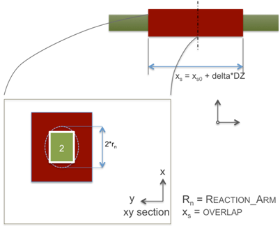
Figure 9: The geometry for a translational joint
The following geometrical properties are important for friction calculations:
| • | The reaction arm, denoted as rn. |
| • | The size of the slider, along the axis of translation, is denoted as, xs0. |
The translational joint can be loaded in several ways, each of which generates a friction force. The total friction force is a sum of each of these effects. For a translational joint, there are four contributing effects:
| • | Friction in the xy plane, caused by the rubbing of the block on the slider, Figure 10(a). |
| • | Friction in the xy plane, caused by the torsion of the block on the slider, Figure 10(b). |
| • | Friction in the yz plane, caused by the bending of the slider, Figure 10(c). |
| • | Friction caused by the assembly preload in the joint. |
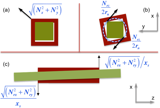
Figure 10: Friction forces caused by reaction forces & moments in a translational joint
Friction in the xy plane, caused by the rubbing of the block on the slider
The normal force acting in the xy plane is shown in Figure 9(a). Nx and Ny are the constraint forces preventing relative motion between block and slider in the x- and y-directions respectively.
The normal force thus is:  . .
The friction force magnitude to axial loading is:  . .
Friction in the xy plane, caused by the torsion of the block on the slider
Referring to Figure 9(b), the torsional moment between the block and the slider causes contact at two of the corners of the block. Assuming that the distance between the contact points is the constant rn, the torsional moment Nrz can be replaced by a couple of equal and opposite forces Nxy acting at each of the contact points.

The friction force due to torsion is:  . .
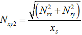
Friction in the xz and yz planes, caused by the bending of the slider
Referring to Figure 9(c), the bending moment tends to bend the block relative to the slider. Contact occurs at two points separated by a distance that is a function of initial_overlap and overlap_delta. Let the distance between the contacts be denoted as xs. Replacing the bending moment by a couple with a moment arm xs gives:
The friction force due to bending is:  . .
Friction caused by the assembly preload in the joint
The force preload is divided by to calculate an equivalent force normal to the contact surface if the joint. Friction forces on the surface are calculated next, using the LuGre function. Thus:
The friction force due to preload is:  . .
The total frictional force in the translational joint is: 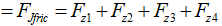 . .
|
| 11. | Friction in a Cylindrical joint. |
Figure 11 below, describes the geometry of a cylindrical joint. A slider with a circular slot, shown in brick red, slides on a circular shaft, shown in green. The z-axis of Marker J on the green shaft defines the axis of translation and rotation. The inset shows an x-y section of the joint cutting through the slider.
The following geometrical properties are important for friction calculations:
| • | The pin radius, denoted as rp. |
| • | The bending moment arm, along the axis of translation, is denoted as, x0. |
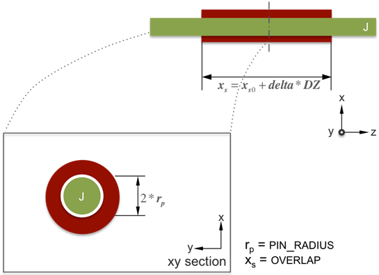
Figure 11: The geometry for a cylindrical joint
The cylindrical joint can be loaded in several ways, each of which generates a friction force. The total friction force is a sum of each of these effects. For a cylindrical joint, there are three contributing effects:
| • | Friction Force/Torque, caused by the radial load, Figure 11(a). |
| • | Friction Force/Torque, caused by the bending of the slider, Figure 11(b). |
| • | Friction Force/Torque, caused by the assembly preload in the joint. |
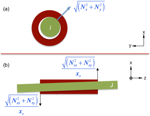
Figure 12: Friction forces caused by reaction forces and moments in a cylindrical joint
Friction Force/Torque, caused by the radial load
The normal force acting in the xy plane is shown in Figure 12(a). Nx and Ny are the constraint forces preventing relative motion between block and slider in the x- and y-directions respectively.
The normal force thus is 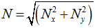 and the slip velocity at the contact point is and the slip velocity at the contact point is  . .
Define the bristle deflections 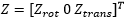 . .
The friction force due to radial loading is  . .
The friction torque due to radial loading is 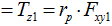 . .
Friction Force/Torque caused by the bending of the slider
Referring to Figure 10(b), the bending moment tends to bend the block relative to the slider. Contact occurs at two points separated by a distance that is a function of initial_overlap and overlap_delta. Let the distance between the contacts be denoted as xs. Replacing the bending moment by a couple with a moment arm xs gives:
The friction force due to bending is  . .
The friction torque due to bending is 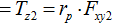 . .
Friction Force/Torque caused by the assembly preload in the joint
The force preload is divided by to calculate an equivalent force normal to the contact surface if the joint. Friction forces on the surface are calculated next, using the LuGre function. Thus:
The friction force due to preload is  . .
The friction torque due to preload is 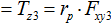 . .
The total circumferential friction force in the cylindrical joint 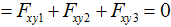 . .
The total axial frictional force in the cylindrical joint 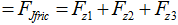 . .
The total frictional torque in the cylindrical joint 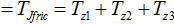 . .
|
| 12. | Friction in a Universal Joint |
A universal joint can be conceptually thought of as being composed of two revolute joints. The axis of one revolute joint is along the I-Yoke, and the axis of the second revolute joint is along the J-Yoke. Friction on each of the yokes is modeled as for a revolute joint. For more information on modeling friction in the revolute joint, see Comment 8.
|
| 13. | Friction in a Spherical joint |
A spherical joint allows rotations about all the three axes and arrests all translational degrees of freedom. Hence, dynamics around a spherical joint can be cast in terms of relative motion on the spherical surface of the ball. A typical loading scenario for a spherical joint is described in Figure 12. In this case, referring to Figure 12 below, the following geometrical properties are important for friction calculations:
| • | The ball radius, denoted as rb. |
The spherical joint can be loaded because of the constraint force between the ball and the socket and the joint assembly preload. The total friction force is a sum of each of these effects. For the sake of simplicity, we define the normal reaction as the sum of the joint reaction force and the preload force. This is represented as  in the figure below. in the figure below.
Let:

The angular velocity of the ball with respect to the socket be 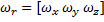 . .
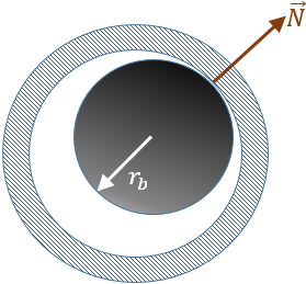
Figure 13: The geometry and friction kinematics for a spherical joint
The components of the slip velocity can be computed in the global coordinate system as follows:
Slip velocity 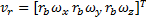 , ,  Bristle states Bristle states  , ,
The frictional force in the spherical joint, following the conventions described in comment 6, is:

And the frictional torque is therefore:
| 14. | Friction in a Hook Joint |
A hook joint can be conceptually thought of as being composed of two revolute joints. The axis of one revolute joint is along the I-Yoke, and the axis of the second revolute joint is along the J-Yoke. Friction on each of the yokes is modeled as for a revolute joint. For more information on modeling friction in the revolute joint, see Comment 8.
|
| • | C. Canudas de Wit, H. Olsson, K. J. Aström, and P. Lischinsky,A New Model for Control of Systems with Friction. IEEE Transactions on Automatic Control, March 1995, vol.40, No.3, pp.419-425. |
| • | Velenis E., Tsiotras P., Canudas-de-Wit C.(2005), "Extension of the LuGre Dynamic Tire Friction Model to 2D Motion", Vehicle System Dynamics, 2005. |
| • | Bliman, P. A. Sorine, M., “Friction modeling by hysteresis operators. Application to Dahl, sticktion and Stribeck effects”, Pitman Research Notes in Mathematics Series, 1993, Issue 286, pages 10 |
| • | Olsson, H. Aström, K. J. Canudas De Wit, C. Gaefvert, M. Lischinsky, P., “Friction Models and Friction Compensation”, European Journal of Control, 1998, Vol. 4; Number 3, pages 176-195 |
| • | J. C. Trinkle, J.-S. Pang, S. Sudarsky, G. Lo, “On Dynamic Multi-Rigid-Body Contact Problems with Coulomb Friction”, ZAMM - Journal of Applied Mathematics and Mechanics / Zeitschrift für Angewandte Mathematik und Mechanik, Volume 77, Issue 4, pp. 267–279, 1997 |
|
Examples
|
|
|
<Force_JointFriction
|
|
id = "1"
|
The Friction force id =1.
|
joint_id = "301001"
|
Friction force associated with revolute joint 301001.
|
mu_static = "0.5"
|
Static friction coefficient (µs) is 0.5.
|
mu_dynamic = "0.3"
|
Dynamic friction coefficient (µd) is 0.3.
|
inactive = "NONE"
|
Friction is active for all analysis modes.
|
stiction_trans_vel = "10."
|
Transition velocity from dynamic friction to stiction is 10 vel. units.
|
effect = "All"
|
Both stiction and dynamic friction effects are to be considered.
|
torque_preload = "0."
|
The friction preload is zero.
|
friction_arm = "7."
|
Moment arm (rn) to compute axial friction torque is 7 length units.
|
pin_radius = "5."
|
Joint pin radius (rp) is 5 length units.
|
bending_reaction_arm = "5."
|
Moment arm (rb) to compute bending moment is 5 length units.
|
inputs = "1111"
|
All preload and reaction forces are considered for friction force calculation.
|
/>
|
|
Pendulum with friction model
|
|
<?xml version="1.0" encoding="ISO-8859-1"?>
<?xml-stylesheet type="text/xsl"
href="http://www.altairhyperworks.com/motionsolve-xml/motionsolve_v1.xsl"?>
<MultiBodySystem
xmlns:xs="http://www.w3.org/2001/XMLSchema-instance"
xs:noNamespaceSchemaLocation="http://www.altairhyperworks.com/motionsolve-xml/motionsolve_v1.xsd"
hw_version = "11.0">
<Messaging
log_option = "Overwrite"
/>
<Model>
<Param_Transient
integrator_type = "DSTIFF"
integr_tol = "0.0001"
h_max = "0.1"
h0_max = "0.005"
h_min = "1.0000E-06"
max_order = "6"
vel_tol_factor = "1000."
rel_abs_tol_ratio = "0.01"
central_difference = "FALSE"
dae_constr_tol = "0.000001"
dae_corrector_maxit = "10"
dae_corrector_minit = "0"
dae_index = "3"
dae_vel_ctrl = "TRUE"
dae_jacob_init = "1"
hht_alpha = "-0.33"
newmark_beta = "0.36"
newmark_gamma = "0.7"
/>
<Param_Unit
force_unit = "NEWTON"
mass_unit = "KILOGRAM"
length_unit = "MILLIMETER"
time_unit = "SECOND"
/>
<Reference_Marker
id = "30101010"
label = "Global Frame"
body_id = "30101"
body_type = "RigidBody"
/>
<Reference_Marker
id = "30101020"
label = "Joint 0-Marker J"
body_id = "30101"
body_type = "RigidBody"
a00 = "-1."
a10 = "0."
a20 = "0."
a02 = "0."
a12 = "1."
a22 = "0."
/>
<Reference_Marker
id = "30102020"
label = "Joint 0-Marker I"
body_id = "30102"
body_type = "RigidBody"
a00 = "-1."
a10 = "0."
a20 = "0."
a02 = "0."
a12 = "1."
a22 = "0."
/>
<Reference_Marker
id = "30102030"
label = "bob-Marker CM"
body_id = "30102"
body_type = "RigidBody"
pos_x = "-100."
pos_y = "0."
pos_z = "0."
/>
<Reference_Marker
id = "73780000"
label = "LPRFMarker/73780000"
body_id = "30102"
body_type = "RigidBody"
/>
<Reference_Marker
id = "90000000"
body_id = "30102"
body_type = "RigidBody"
pos_x = "-100."
pos_y = "0."
pos_z = "0."
a00 = "0."
a10 = "1."
a20 = "0."
a02 = "1."
a12 = "0."
a22 = "0."
/>
<Reference_Marker
id = "90000001"
body_id = "30102"
body_type = "RigidBody"
pos_x = "-100."
pos_y = "0."
pos_z = "0."
a00 = "0."
a10 = "1."
a20 = "0."
a02 = "1."
a12 = "0."
a22 = "0."
/>
<Reference_Marker
id = "90000002"
body_id = "30102"
body_type = "RigidBody"
a00 = "0."
a10 = "-1."
a20 = "0."
a02 = "-1."
a12 = "0."
a22 = "0."
/>
<Reference_Marker
id = "90000012"
body_id = "30102"
body_type = "RigidBody"
pos_x = "-100."
pos_y = "-9.86361"
pos_z = "-9.86361"
/>
|
<Body_Rigid
id = "30101"
label = "Ground"
IsGround = "TRUE"
/>
<Body_Rigid
id = "30102"
label = "bob"
cg_id = "30102030"
im_id = "30102030"
lprf_id = "73780000"
mass = "1."
inertia_xx = "1000."
inertia_yy = "1000."
inertia_zz = "1000."
/>
<Constraint_Joint
id = "301001"
label = "Joint 0"
type = "REVOLUTE"
i_marker_id = "30102020"
j_marker_id = "30101020"
/>
<Force_Gravity
grav_x = "0."
grav_y = "0."
grav_z = "-9810."
/>
<Force_JointFriction
id = "1"
joint_id = "301001"
mu_static = "0.5"
mu_dynamic = "0.3"
inactive = "NONE"
stiction_trans_vel = "10."
effect = "All"
torque_preload = "0."
friction_arm = "7."
pin_radius = "5."
bending_reaction_arm= "5."
inputs = "1111"
/>
<Post_Request
id = "1"
comment = "Joint omega"
type = "EXPRESSION"
expr1 = "NULL"
expr2 = "WZ(30102020,30101020,30101020)"
expr3 = "NULL"
expr4 = "NULL"
expr5 = "NULL"
expr6 = "NULL"
expr7 = "NULL"
expr8 = "NULL"
/>
<Post_Request
id = "2"
comment = "Joint friction"
type = "EXPRESSION"
expr1 = "NULL"
expr2 = "FRICTION(1,1)"
expr3 = "FRICTION(1,2)"
expr4 = "FRICTION(1,3)"
expr5 = "NULL"
expr6 = "FRICTION(1,4)"
expr7 = "FRICTION(1,5)"
expr8 = "FRICTION(1,6)"
/>
<Post_Graphic
id = "90000"
type = "Frustum"
center_marker_id = "90000000"
top_radius = "1."
bottom_radius = "1."
length = "100."
ends_type = "OPEN"
refinement_level = "2"
is_material_inside = "TRUE"
/>
<Post_Graphic
id = "90001"
type = "Frustum"
center_marker_id = "90000001"
top_radius = "0."
bottom_radius = "1."
length = "0.001"
ends_type = "OPEN"
refinement_level = "2"
is_material_inside = "TRUE"
/>
<Post_Graphic
id = "90002"
type = "Frustum"
center_marker_id = "90000002"
top_radius = "0."
bottom_radius = "1."
length = "0.001"
ends_type = "OPEN"
refinement_level = "2"
is_material_inside = "TRUE"
/>
<Post_Graphic
id = "90012"
type = "BoxDefinedFromCorner"
corner_marker_id = "90000012"
length_x = "20."
length_y = "20."
length_z = "19.86361"
is_material_inside = "TRUE"
/>
</Model>
<Command
time_out = "999999"> <!--In SECONDS-->
<H3DOutput
switch_on = "TRUE"
/>
<ResOutput
plt_file = "TRUE"
/>
<Simulate
analysis_type = "Transient"
end_time = "5."
num_step = "1000"
/>
</Command>
</MultiBodySystem>
|
|


