|
»Click here to display Table of Contents«
|

/INTER/TYPE24 |

|

|

|

|
|
/INTER/TYPE24 |
|
|

|

|
|
»Click here to display Table of Contents«
|
/INTER/TYPE24 |
|
|
|
|
|
/INTER/TYPE24 |
|
|
|
|
Block Format Keyword
/INTER/TYPE24 - Interface Type 24
Description
TYPE24 is a general nodes to surface contact interface using the penalty method. Penalty stiffness is constant and therefore the time step is not affected (for standard penalty stiffness). Solid elements are given a zero gap. Three types of inputs contacts can be defined: single surface, surface to surface, or nodes to surface. This contact interface can replace interface TYPE3, TYPE5, TYPE7, or TYPE20. For implicit solution, this interface TYPE24 is only available with SMP.
(1) |
(2) |
(3) |
(4) |
(5) |
(6) |
(7) |
(8) |
(9) |
(10) |
/INTER/TYPE24/inter_ID/unit_ID |
|||||||||
inter_title |
|||||||||
surf_ID1 |
surf_ID2 |
Istf |
|
|
|
|
|
|
|
grnd_IDs |
|
|
|
Gap_max_s |
Gap_max_m |
||||
Stmin |
Stmax |
Igap0 |
Ipen0 |
Ipen_max |
|
||||
(1) |
(2) |
(3) |
(4) |
(5) |
(6) |
(7) |
(8) |
(9) |
(10) |
Stfac |
Fric |
|
|
Tstart |
Tstop |
||||
IBC |
|
|
Inacti |
VISS |
|
|
|||
Ifric |
Ifiltr |
Xfreq |
|
sens_ID |
|
|
|||
(1) |
(2) |
(3) |
(4) |
(5) |
(6) |
(7) |
(8) |
(9) |
(10) |
C1 |
C2 |
C3 |
C4 |
C5 |
|||||
(1) |
(2) |
(3) |
(4) |
(5) |
(6) |
(7) |
(8) |
(9) |
(10) |
C6 |
|
|
|
|
|||||
|
|
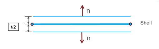
grnd_IDs > 0 is used to define node to surface contact type, but it may also be used in other contact types. In that case, the node group will be added simply as supplementary slave nodes, which is useful when users want to add spring element nodes, master node of rigid body, etc. into the contact (as slave nodes). If the surface is defined with shells, two contact segments (shifted by half thickness (t)) with opposite normal directions will be generated:
In case of SPMD, each master segment defined by surf_IDi (i=1,2) must be associated to an element (possibly to a void element). In cases where quadratic elements are used, it is recommended to define the surfaces by using /SURF/PART/EXT as in that case, middle nodes of quadratic elements are used in the contact treatment. The surface definition /SURF/PART/ALL is not available with TYPE24.
For each contact, to make nonlinear iteration convergence easier, smaller initial stiffness is used; for the function of the reaction of the contacting parts (with increasing penetration or rebound), the stiffness will be adjusted, but is always smaller than the input stiffness, then:
For each interface stiffness definition: Km: master segment stiffness
Ks: Slave node stiffness is an equivalent nodal stiffness considered for interface TYPE24, and computed as:
While, S is the segment area, V is the volume of the solid, B is the Bulk Modulus, t is the thickness of the shell The Stfac value can be larger than 1.0. There is no limitation value to the stiffness factor (a value larger than 1.0 can reduce the initial time step).
If Implicit Analysis is to be considered (defined by /IMPLICIT), the default value is Istf= 4; Istf = 6 is recommended for flexible or bending dominated structures.
While,
If the slave node is connected to multiple shells and/or beams or trusses, the largest computed slave gap is used. gm and gs are limited separately by Gap_max_m and Gap_max_s before the gap is computed.
While an adhesion force is computed as follows:
Where, p is the pressure of the normal force on the master segment V is the tangential velocity of the slave node. Currently, the coefficients C1 ~ C6 are used to define a variable friction coefficient The following formulations are available:
Where,
If Ifiltr = 1, 2 or 3, the tangential forces are smoothed using a filter:
Where,
The filtering coefficient Xfreq should have a value between 0 and 1.
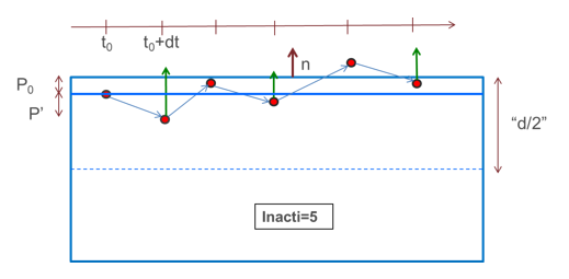
The master segment position is restored only in case of rebound larger than P0. In the opposite case, when slave node continues to penetrate, the penetration is computed as:
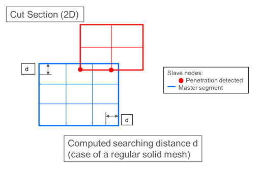
Shells and thick shells: initial intersections should be avoided, as they will lead to wrong direction of contact force and possible slave nodes anchorage. Solids: by default, the distance which is considered for searching the initial penetration is compute as:
While for each master segment, V is the volume of the connected solid element, A is the segment area, Ledge (edge= 1 to 4) are the lengths of the edges of the segment.
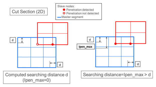
Maximum initial penetration Ipen_max:
When the contact type is asymmetric surface to surface, the output normal contact forces in Time History are calculated correctly, if the two surfaces are well separated.
|


 , standard -3dB filter, with
  , and
, and 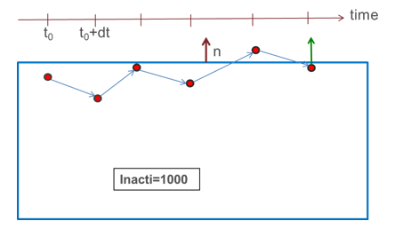
 is an estimation of the depth of the solid element connected to the segment (limited to the size of the segment).