In this tutorial, shape optimization on a solid model will be performed using the free-shape optimization method along with manufacturing constraints, such as symmetry and mesh barrier constraints. The objective of this optimization is to reduce the stress by changing the geometry of the model.
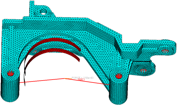
In this tutorial, you will learn to:
| • | Setup a free-shape optimization problem with manufacturing constraints |
| • | Post-process free-shape optimization results in HyperView |
Exercise
Setting Up a Free-shape Optimization Problem with Manufacturing Constraints
Step 1: Launch HyperMesh Desktop, Set the User Profile, and Retrieve the Model
| 1. | Launch HyperMesh Desktop. |
| 2. | Choose OptiStruct in the User Profiles dialog and click OK. This loads the user profile. It includes the appropriate template, macro menu, and import reader, paring down the functionality of HyperMesh to what is relevant for generating models for OptiStruct. |
User Profiles can also be accessed from the Preferences menu on the toolbar.
| 3. | From the File menu, select Open > Model. |
| 4. | Select the freeshape3d_mfg.hm file you saved to your working directory from the optistruct.zip file. Refer to Accessing the Model Files. |
| 5. | Click Open. The freeshape3D_mfg.hm database is loaded into the current HyperMesh session, replacing any existing data. |
The location of freeshape3D_mfg.hm displays in the file: field.
Step 2: Create Free-shape Design Variables (DSHAPE Cards)
| 1. | From the Analysis page, click optimization. |
| 3. | In the create subpanel, click desvar=, and enter shape. |
| 4. | Click nodes and select the by sets check the box next to shape_nodes. |
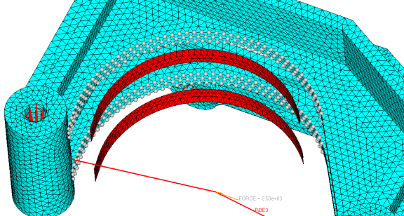
Free-shape design space
| 7. | Click the parameters subpanel and select the direction as grow. |
| 9. | Set nsmooth to 10 and click update. |

| 10. | Click return twice to exit the panel. |
Step 3: Convert Existing Shell Elements to Create the Barrier Mesh Face (BMFACE)
| 2. | Enter the elem types panel. |
| 3. | Click elems to get the extended entity list. |
| 5. | Check the box next to barrier. |
| 6. | On the 2D & 3D subpanel, click CTRIA3 in the field next to tria3. |
| 7. | Select BMFACE from the list of options. |
| 8. | Click CQUAD4 in the field next to quad4. |
| 9. | Select BMFACE from the list of options. |
Step 4: Define the 1-Plane Symmetry Constraint
The manufacturing constraint options for free-shape are: (Draw direction constraint, Extrusion constraint, Pattern grouping: 1-plane symmetry constraint, Maximum growing/shrinking distance control, Side constraint, and Mesh barrier constraint).
| 1. | From the Analysis page, click optimization. |
| 2. | Click free shape; make sure that the desvar selected is shape. |
| 3. | Click pattern grouping in the free shape panel. |
| 4. | Select the pattern type: 1-pln sym. |
The 1-plane symmetry constraints in free-shape will produce symmetric designs regardless of the initial mesh, boundary conditions or loads. The plane of symmetry is defined by specifying the anchor and the first nodes. The plane of symmetry will then be perpendicular to the vector from the anchor node to the first node and pass through the anchor node.
| 5. | Click anchor node, input the node id= 1, and press ENTER. This selects the node with the ID of 1. |
| 6. | Click first node and input the node id= 2. This selects the node with the ID of 2. |
| 7. | Click update to update the design variables. This completes the definition of the symmetry constraint. |
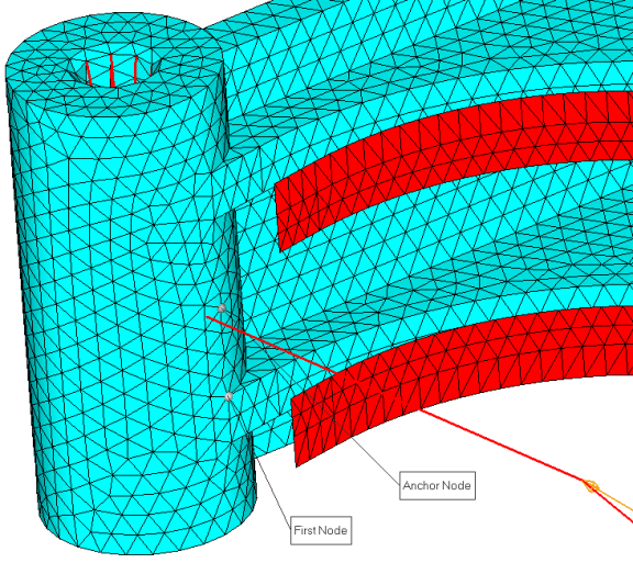
Defining 1-plane symmetry
Step 5: Define the Mesh Barrier (sidecon) Constraint
A mesh barrier constraint allows control on the total deformation extent of a design boundary/surface; mesh barrier will constrain the design boundary/surface to deform within the restricted design space and never penetrate the barrier.
The barrier should be constructed by shell elements with the smallest number of elements possible.
For this exercise, the mesh barrier was already created and the component name is barrier.
| 1. | Click sidecon in the free shape panel. |
| 2. | Click desvar = and select shape. |
| 3. | Click Barrier mesh: component= and select barrier from the list. |
| 5. | Click return to go back to the main menu. |
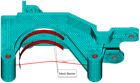
Mesh barrier component
Step 6: Define Responses for Optimization
| 1. | Click the responses panel. |
| 2. | For response=, enter Stress. |
| 3. | Set the response type to static stress. |
| 4. | Switch from props to elems. |
| 5. | Click elems and click by sets. |
| 6. | Check the box next to stress and click select. |
| 7. | Choose von mises and click create. |
| 8. | Click response= and assign mass. |
| 9. | Set the response type to mass. |
| 11. | Click return to go back to the optimization panel. |
Step 7: Define Constraints for Optimization
| 1. | Select the dconstraints panel. |
| 2. | Click constraint= and enter the name stress. |
| 3. | Click response= select stress. |
| 4. | Activate upper bound = and assign a value 62. |
| 5. | Click loadsteps, activate ls2, and click select. |
Step 8: Define the Objective Function
| 1. | Choose the objective panel. |
| 2. | Click the left-most toggle and select min. |
| 3. | Click response= and select mass. |
| 5. | Click return twice to go back to the main menu. |
Step 9: Define the SHAPE Card
Only displacement and stress results are available in the _s#.h3d file by default. In order to look at stress results on top of a shape change that was applied to the model in HyperView, a SHAPE card needs to be defined.
| 1. | From the Analysis page, select the control cards panel. |
| 2. | Click next three times and select SHAPE. |
| 3. | Set format to h3d and both TYPE and OPTION to ALL. |
| 4. | Click return twice to go back to the main menu. |
Step 10: Launch OptiStruct
| 1. | From the Analysis page, click OptiStruct. |
| 2. | Click save as following the input file: field. |
| 3. | Select the directory where you would like to write the OptiStruct model file and enter the name for the model, freeshape3d_mfgopt.fem, in the File name: field. |
The name and location of the freeshape3d_mfgopt.fem file displays in the input file: field.
| 5. | Set the export options toggle to all. |
| 6. | Set the run options toggle to optimization. |
| 7. | Set the memory options toggle to memory default. |
| 8. | Click OptiStruct. This launches an OptiStruct run in a separate (DOS or UNIX) shell. |
If the optimization was successful, no error messages are reported to the shell. The optimization is complete when the message Processing complete appears in the shell.
Post-processing Free-shape Optimization Results in HyperView
This section describes how to view the results in HyperView which will be launched from within the OptiStruct panel of HyperMesh.
HyperView is a complete post-processing and visualization environment for finite element analysis (FEA), multi-body system simulation, video and engineering data.
Step 11: View Shape Results
| 1. | While in the OptiStruct panel of the Analysis page, click HyperView. |
Note that the message window pops up to indicate that freeshape3d_mfgopt_des.h3d and freeshape3d_mfgopt_s4.h3d are opened.
| 2. | Click Close to close the window. |
freeshape3d_mfgopt_des.h3d will be opened in page 1 and
freeshape3d_mfgopt_s4.h3d will be opened in page 2 of HyperView.
| 3. | Click the arrow  to move to page 2. to move to page 2. |
| 4. | From the Graphics menu, click Select Load Case. |
This opens the Load Case and Simulation Selection dialog which is also accessible from the lower right portion of the status bar.
| 5. | Select Iteration14 from beneath Simulation (load final iteration results). |
| 7. | Go to the Deformed panel  . . |
| 8. | Set the Result type: to Shape change(v). |
| 9. | Click Apply. Shape optimization results are applied to the model. |
Step 12: View a Contour Plot of the Stress on Top of the Shape Optimized Model
| 1. | Go to the Contour panel  and select Element Stresses (2D & 3D) (t) as the Result type:. and select Element Stresses (2D & 3D) (t) as the Result type:. |
| 2. | Select von Mises as the stress type. |
| 3. | Click Elements, click By set, and select the set stress. |
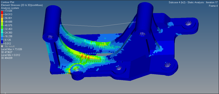
von Mises stress contour on the final shape.
See Also:
OptiStruct Tutorials


