| 1. | The identifier must be unique in each element family, but it is advised to have a unique element identifier in the global model for each element type. |
| 2. | More than one spring block can be used to define a part. |
| 3. | Joint properties are defined in a local coordinate system of the joint element. |
| 4. | The total number of joint DOF computed in the local coordinate system frame is six: |
| 5. | Blocked and free DOF are distinguished for each joint type. |
| 6. | The blocked DOF are characterized by a constant stiffness. By default if a null value is specified, the value of the stiffness is automatically computed in order to preserve the time step. |
| 7. | The translational and rotational DOF are defined as follows: |
where dx1 and dx2 are total displacements of two joint nodes in the local coordinate system.

where  and and  are total relative rotations of two connected body axes, with respect to the local coordinate system of the joint. are total relative rotations of two connected body axes, with respect to the local coordinate system of the joint.
| 8. | Forces and moments calculation: |
| • | The force in direction  is computed as: is computed as: |
Linear spring:
Kti : translational stiffness 
Cti : translational viscosity 
Nonlinear spring:
| • | The moment in  direction is computed as: direction is computed as: |
Linear spring:
Kri: rotational stiffness 
Cri: rotational viscosity 
Nonlinear spring:
| • | The joint length may be, but is not necessarily equal to 0. It is recommended; however, to use a 0 length spring to define a spherical joint or a universal joint. |
| • | To satisfy the global balance of moments in a general case, correction terms in the rotational DOF are calculated as follows: |
Joints do not have user-defined mass or inertia, so the nodal time step is always used.
| • | There are two ways to introduce viscous damping: |
| ➢ | Defining a critical damping (for blocked DOF only): |
Viscous damping is defined in terms of the critical damping factor. The critical damping coefficient is calculated using the blocking stiffness value of the element. The mass and inertia are equal to half of the values for each rigid body connected to the joint. The approximation is then satisfactory, if only one joint is connected to each rigid body. Otherwise, the critical damping is over-estimated; in which case, the damping factor in the RADIOSS input should be decreased. The same damping is applied to all blocked DOF.
| ➢ | User-defined constant or non-linear damping: |
It is possible to define independent damping parameters for each free DOF.
| 9. | Coefficients Kti and Kri are used as constant stiffness, if there are no user-defined functions. If a function number in any DOF is not 0, the corresponding stiffness coefficient becomes a scale factor for the function. |
| 10. | Coefficients Cti and Cri are used as linear viscosity coefficients. if there are no user-defined functions. If a function number in any DOF is not 0, the corresponding coefficient becomes a scale factor for the function. |
| 11. | If a non-zero value is specified for SDi-or SDi+, then an additional penalty force is applied to prevent the displacement to exceed SDi+ for positive displacement and SDi- for negative displacement. This penalty force is computed using Kfti. |
| 12. | If a non-zero value is specified for SAi-or SAi+, then an additional penalty moment is applied to prevent the angle to exceed SAi+ for positive rotation or SAi- for negative rotation. This penalty moment is computed using Kfri. |
| 13. | If Kn = 0, the blocking stiffness area is automatically computed at the beginning of the computation for both translational and rotational blocked DOF, in order to preserve the time step. These values are also selected according to the physics and must be higher than the stiffness of the neighboring elements. |
| 14. | If Kn = 0, then Scf is a scaling factor applied to both translational and rotational blocking stiffness. If Kn > 0, then Scf is applied only on blocking rotational stiffness. This parameter can be used to manually adjust the blocking stiffness in rotation. |
| 15. | If sens_ID is defined, the joint becomes fully blocked (all DOF) when the sensor is activated. |
| 16. | FFi and FMi are used as constant friction force and moment, if there are no user-defined functions. If the friction function number is not 0, FMi and FFi become a scale factor for the functions (default = 1.0). |
| 17. | Friction is not activated, if Kfti or Kfri are not defined. |
| 18. | If skew_ID1 is non-zero, the initial local coordinate system is defined by skew_ID1. If skew_ID1 = 0, the local coordinate system is computed according to the additional nodes of the spring. Refer to /SPRING for more information. |
| 19. | If skew_ID2 is non-zero, rotation angles of the joint are initialized according the rotation between skew_ID1 and skew_ID2. Values of the initial angles can be check in the Starter output file. For revolute (Type 2), cylindrical (Type 3) and planar (Type 4) joints only  can be initialized. The first axis of skew_ID1 and skew_ID2 must be parallel. can be initialized. The first axis of skew_ID1 and skew_ID2 must be parallel. |
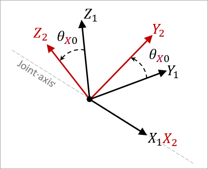
Computation of initial rotation angle for revolute joint (type2)
| 20. | If skew_ID2 is non-zero and skew_ID1 =0, then skew_ID1 is the global coordinate system. |
| 21. | The local coordinate system orientation is updated according node_ID1 (/SPRING) rotation. |
|


 or None

