|
»Click here to display Table of Contents«
|

RELOC |

|

|

|

|
|
RELOC |
|
|

|

|
|
»Click here to display Table of Contents«
|
RELOC |
|
|
|
|
|
RELOC |
|
|
|
|
The RELOC bulk data entry can be used to geometrically map parts (for example, elements and grids) from one location to another. This entry allows you to define mapping as MOVE (translation), ROTATE, MIRROR, or MATCH (as an arbitrary transformation which matches grids from one group to similar grids in another group). Each transformation can be defined by a combination of GRID points and numeric values (real numbers) representing distances and angles. The grid ID fields can be input as either numeric (positive integer) or fully qualified references to grid points in the model. Numeric references (without part name) specify grid points in the global part.
Format
The format of this entry depends on the content of string input in TYPE field (field 3); the various versions are listed below. Note that dx, dy, dz, ang_x, ang_y, and ang_z fields should contain real numbers (integers or blank are not allowed for these fields).
(1) |
(2) |
(3) |
(4) |
(5) |
(6) |
(7) |
(8) |
(9) |
(10) |
RELOC |
ID |
TYPE |
GID1 |
GID2 |
|
|
|
|
|
(1) |
(2) |
(3) |
(4) |
(5) |
(6) |
(7) |
(8) |
(9) |
(10) |
RELOC |
ID |
TYPE |
dx |
dy |
dz |
|
|
|
|
(1) |
(2) |
(3) |
(4) |
(5) |
(6) |
(7) |
(8) |
(9) |
(10) |
RELOC |
ID |
TYPE |
GID1 |
ang_x |
ang_y |
ang_z |
|
|
|
(1) |
(2) |
(3) |
(4) |
(5) |
(6) |
(7) |
(8) |
(9) |
(10) |
RELOC |
ID |
TYPE |
GID1 |
GID2 |
angle |
|
|
|
|
(1) |
(2) |
(3) |
(4) |
(5) |
(6) |
(7) |
(8) |
(9) |
(10) |
RELOC |
ID |
TYPE |
GID1 |
GID2 |
GID3 |
GID4 |
|
|
|
(1) |
(2) |
(3) |
(4) |
(5) |
(6) |
(7) |
(8) |
(9) |
(10) |
RELOC |
ID |
TYPE |
GID1 |
GID2 |
GID3 |
|
|
|
|
(1) |
(2) |
(3) |
(4) |
(5) |
(6) |
(7) |
(8) |
(9) |
(10) |
RELOC |
ID |
TYPE |
GIDA1 |
GIDA2 |
GIDA3 |
GIDB1 |
GIDB2 |
GIDB3 |
|
(1) |
(2) |
(3) |
(4) |
(5) |
(6) |
(7) |
(8) |
(9) |
(10) |
RELOC |
ID |
TYPE |
GIDA1 |
GIDA2 |
GIDB1 |
GIDB2 |
|
|
|
(1) |
(2) |
(3) |
(4) |
(5) |
(6) |
(7) |
(8) |
(9) |
(10) |
RELOC |
ID |
TYPE |
GIDA1 |
GIDA2 |
GIDA3 |
|
|
|
|
(1) |
(2) |
(3) |
(4) |
(5) |
(6) |
(7) |
(8) |
(9) |
(10) |
RELOC |
ID |
TYPE |
GIDA1 |
GIDA2 |
GIDA3 |
GIDB1 |
GIDB2 |
GIDB3 |
|
(1) |
(2) |
(3) |
(4) |
(5) |
(6) |
(7) |
(8) |
(9) |
(10) |
RELOC |
ID |
TYPE |
GID1 |
GID2 |
|
|
|
|
|
(1) |
(2) |
(3) |
(4) |
(5) |
(6) |
(7) |
(8) |
(9) |
(10) |
RELOC |
ID |
TYPE |
GIDA1 |
GIDA2 |
GIDB1 |
GIDB2 |
|
|
|
|
Field |
Contents |
|
ID |
Set identification number. (Integer > 0) |
|
TYPE |
This field specifies the type of mapping between grid points in a model. The format of the RELOC card is different for different values of the TYPE field (see Comment 2 for detailed information on each option). (MOVE, ROTATE, MATCH, or MIRROR) |
|
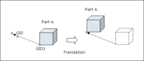
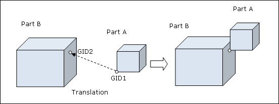
Translation (Format 1) |
||
GID1 |
Grid point identification number for translation to the reference point location. Grid point GID1 is moved from its original location to the GID2 location. (Integer > 0 or <PartName.number>) See comment 4. |
|
GID2 |
Reference grid point identification number for translation. GID2 is used as a reference point to move another grid point (GID1) from its original location to the GID2 location. (Integer > 0 or <PartName.number>) See comment 4. |
|
Translation (Format 2) |
||
dx, dy, dz |
Defines the distance that the referenced part (INSTNCE entry) should be translated in the basic coordinate system. Each entry specifies the corresponding distance moved in the X, Y, and Z axes, respectively. See comment 2. No default (Real) |
|
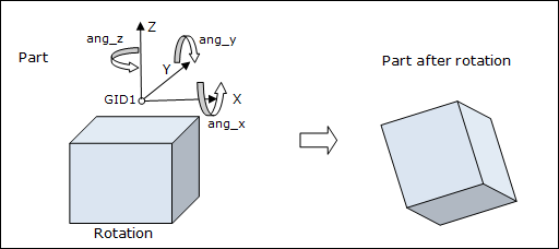
Rotation (Format 1) |
||
GID1 |
Specifies the identification number of a grid point that will be used as a center of rotation based on the angles specified in the following fields. (Integer > 0 or <PartName.number>) See comment 4. |
|
ang_x, |
Defines the angle (in degrees) of rotation about the X, Y, and Z axes, respectively with the grid point (GID1) as the center of rotation. In a 2D model, only ang_z is specified. See comment 2. No default (Real) |
|
Rotation (Format 2) |
||
GID1,GID2 |
Specifies the identification number of grid points that will be used as axis of rotation. (Integer > 0 or <PartName.number>) See comment 4. |
|
angle |
Defines the angle (in degrees) of rotation about the axis defined by GID1 and GID2. (Real or blank) |
|
Rotation (Format 3) |
||
GID1,GID2 |
Specifies the identification number of grid points that will be used as axis of rotation. (Integer > 0 or <PartName.number>) See comment 4. |
|
GID3 |
Specifies the identification number of the grid point to be rotated. (Integer > 0 or <PartName.number>) |
|
GID4 |
Specifies the identification number of the grid point which, together with GID1 and GID2, defines a plane to which GID3 is to be rotated. (Integer > 0 or <PartName.number>) |
|
Rotation (Format 4) |
||
GID1 |
Specifies the identification number of the grid point that will be used as center of rotation. (Integer > 0 or <PartName.number>) See comment 4. |
|
GID2 |
Specifies the identification number of the grid point to be rotated. (Integer > 0 or <PartName.number>) |
|
GID3 |
Specifies the identification number of the grid point which, together with GID1, defines a line to which GID3 is to be rotated. (Integer > 0 or <PartName.number>) |
|
Matching (Format 1) |
||
GIDA1, |
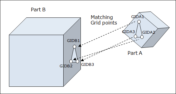
Specifies the identification numbers of grid points (initial location) that will be moved to match with the corresponding grid points GIDB1,2,3 (final location, defined in the following fields). Any rotation, translation or mirroring required to complete this matching process is accomplished internally by OptiStruct. These three grid points cannot be collinear. (Integer > 0 or <PartName.number>) See comment 4. |
|
GIDB1, |
Specifies the identification numbers of grid points which will be matched with the corresponding grid points defined in the GIDA1,2,3 fields. Any rotation, translation or mirroring required to complete this matching process is accomplished internally by OptiStruct. These three grid points cannot be collinear. (Integer > 0 or <PartName.number>) See comment 4. |
|
Matching (Format 2) |
||
GIDA1, |
Specifies the identification numbers of grid points (initial location) that will be moved to match with the corresponding grid points GIDB1,2 (final location, defined in the following fields). Any rotation, translation or mirroring required to complete this matching process is accomplished internally by OptiStruct. These two grid points cannot be coincident. (Integer > 0 or <PartName.number>) |
|
GIDB1, |
Specifies the identification numbers of grid points which will be matched with the corresponding grid points defined in the GIDA1,2 fields. Any rotation, translation or mirroring required to complete this matching process is accomplished internally by OptiStruct. These two grid points cannot be coincident. (Integer > 0 or <PartName.number>) |
|
Mirroring (Format 1) |
||
GIDA1, |
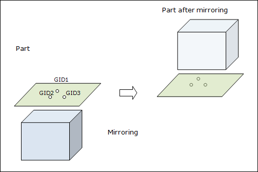
Specifies the identification numbers of grid points about which the entire part (defined via INSTNCE) will be laterally mirrored (flipped) by 180 degrees. The grid points GIDA1,2,3 define an absolute plane of symmetry flip. Any rotation or translation required to complete this mirroring process is accomplished internally by OptiStruct. The three grid points specified for mirroring cannot be collinear. In a 2D model, only GIDA1 and GIDA2 should be specified. (Integer > 0 or <PartName.number>) See comment 4. |
|
Mirroring (Format 2) |
||
GIDA1, |
Specifies the identification numbers of grid points (initial location) that will be moved to match with the corresponding grid points GIDB1,2,3 (final location, defined in the following fields). Any rotation, translation or mirroring required to complete this matching process is accomplished internally by OptiStruct. These three grid points cannot be collinear. (Integer > 0 or <PartName.number>) |
|
GIDB1, |
Specifies the identification numbers of grid points which will be matched with the corresponding grid points defined in the GIDA1,2,3 fields. After matching, the entire part (defined via INSTNCE) will be laterally mirrored (flipped) by 180 degrees. The grid points GIDB1,2,3 define an absolute plane of symmetry flip. Any rotation, translation or mirroring required to complete this matching process is accomplished internally by OptiStruct. These three grid points cannot be collinear. (Integer > 0 or <PartName.number>) |
|
Mirroring (Format 3) |
||
GID1,GID2 |
Specifies the identification number of grid points that will be used as axis of symmetry for mirroring (Integer > 0 or <PartName.number>) See comment 4. (Integer > 0 or <PartName.number>) |
|
Mirroring (Format 4) |
||
GIDA1, |
Specifies the identification numbers of grid points (initial location) that will be moved to match with the corresponding grid points GIDB1,2 (final location, defined in the following fields). Any rotation, translation or mirroring required to complete this matching process is accomplished internally by OptiStruct. These two grid points cannot be coincident. (Integer > 0 or <PartName.number>) |
|
GIDB1, |
Specifies the identification numbers of grid points which will be matched with the corresponding grid points defined in the GIDA1,2 fields. After matching, the entire part (defined via INSTNCE) will be laterally mirrored (flipped) by 180 degrees. The grid points GIDB1,2 define an absolute axis of symmetry flip. Any rotation, translation or mirroring required to complete this matching process is accomplished internally by OptiStruct. These two grid points cannot be coincident. (Integer > 0 or <PartName.number>) |
|
| 1. | A RELOC entry can be referenced by a INSTNCE entry to define the location of a part in the full model. Additionally, the PERBC entry references the RELOC entry to define geometric relationship between two sets of boundary grid points. |
| 2. | The following illustrations depict part relocation examples for each of the four TYPE field options. All grid point ID’s used on the RELOC entry can belong to any part in the model. Only their initial locations are relevant. All RELOC entries are evaluated before any parts are moved. This may not always produce the expected result in some cases as the sequence of moves affects the final part locations. For example, if RELOC, MATCH is defined using three grid points on part A and three grid points in part B, this may not result in a final structure with the two parts being connected, if part B is moved again after this matching process. To avoid such cases, it is strongly recommended to assign the grid points that define the initial location to a part that has to be moved and the grid points that define the final location, to a part that will not be moved (for example, the global structure). |
Translation - Format 1:
Format 1 (Special case, assumes that Part B does not relocate)
Translation - Format 2:
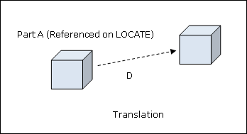
![]()
Where, D is the distance moved by the part referenced on the INSTNCE entry, and dx, dy and dz are the distances moved by the part along the X, Y and Z axes.
Rotation - Format 1:
Matching - Format 1:
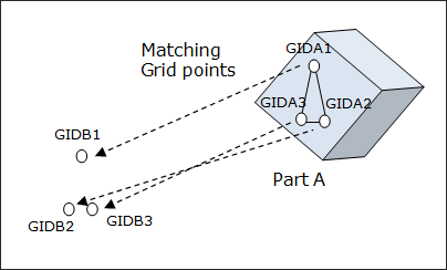
Format 1 (Special case – Part B does not relocate)
Mirroring - Format 1:
| 3. | In a 2D model, only two TYPE options are allowed: ROTATE and MIRROR. All grid points in the model should have the same Z coordinate. Rotation and mirroring are defined in the X-Y plane. |
Rotation in a 2D model defined in the X-Y plane
(1) |
(2) |
(3) |
(4) |
(5) |
(6) |
(7) |
(8) |
(9) |
(10) |
RELOC |
ID |
ROTATE |
GID1 |
|
|
ang_z |
|
|
|
Mirroring in a 2D model defined in the X-Y plane
(1) |
(2) |
(3) |
(4) |
(5) |
(6) |
(7) |
(8) |
(9) |
(10) |
RELOC |
ID |
MIRROR |
GIDA1 |
GIDA2 |
|
|
|
|
|
In special cases where a model is defined in the X-Y plane (or a plane parallel to the X-Y plane), all RELOC type options (MOVE, MATCH, ROTATE and MIRROR) are supported to relocate the part in the same plane in the same way as a 2 dimensional transformation. In such cases, simplified card formats are implemented to provide easier specifications of relocation.
Note: all grid points in the model should have the same Z coordinate. Rotation and mirroring are defined in the X-Y plane.
| 4. | Supported local entries in specific parts can be referenced by the use of “fully qualified references” on RELOC entries in the model. A fully qualified reference (“PartName.number”) is similar to the format of a numeric reference. “PartName” is the name of the part that contains the referenced local entry (part names are defined on the BEGIN bulk data entry in the model). “number” is the identification number of a referenced local entry in the part “PartName”. See Parts and Instances in the User’s Guide for detailed information on the use of fully qualified references. |
| 5. | Relocation is computed internally using initial locations of all GRIDs specified on the corresponding RELOC entry. It is not affected by any movement of parts due to the INSTNCE entry. For example, the entry RELOC, 5, aaa.1, bbb.2 does not indicate that parts aaa and bbb will be connected together after all the INSTNCE cards are processed. |
| 6. | For RELOC entries using GRID match (MATCH formats 1,2 and MIRROR formats 2,4), the starting configuration should match the ending configuration. That is, the distances between matched GRID’s should be the same prior to and after relocation (for example, GIDA1, GIDA2 to GIDB1, GIDB2). |
See Also: