|
»Click here to display Table of Contents«
|

RFORCE |

|

|

|

|
|
RFORCE |
|
|

|

|
|
»Click here to display Table of Contents«
|
RFORCE |
|
|
|
|
|
RFORCE |
|
|
|
|
Bulk Data Entry
RFORCE – Rotational Force
Description
Defines a static loading condition due to a centrifugal force field. It can also be used to define the EXCITEID field (Amplitude “A”) of dynamic loads in RLOAD1, RLOAD2, TLOAD1 and TLOAD2 bulk data entries. RFORCE is used as a linear dead-load in Large Displacement Nonlinear Analysis.
Format
(1) |
(2) |
(3) |
(4) |
(5) |
(6) |
(7) |
(8) |
(9) |
(10) |
RFORCE |
SID |
G |
CID |
A |
R1 |
R2 |
R3 |
|
|
|
RACC |
|
IDRF |
|
|
|
|
|
|
|
Field |
Contents |
SID |
Load set identification number. No default (Integer > 0) |
G |
Grid point identification number through which the rotation vector acts. = 0 or blank means the basic coordinate system origin. Default = 0 (Integer > 0) |
CID |
Coordinate system defining the components of the rotation vector. = 0 or blank signifies that the rotation vector acts at the origin of the basic coordinate system. Default = 0 (Integer > 0) |
A |
Scale factor of the rotational velocity in revolutions per unit time. Default = 0.0 (Real) |
R1,R2,R3 |
Rectangular components of rotation direction vector. The vector defined will pass through point G. No default (Real; R12 + R22 + R32 > 0.0) |
RACC |
Scale factor of the rotational acceleration in revolutions per unit time squared. The continuation line containing RACC is optional. (Real) |
IDRF |
Set Identification Number of an element set (SET bulk data entry) to which this RFORCE entry applies. This field can be used to define different Rotational forces to different parts of the model. |
| 1. | The rotational forces that are created with an RFORCE entry for a constant angular velocity (A), act in the positive radial direction. They represent the initial forces on the structure due to a constant angular velocity. The rotational forces defined for a constant angular acceleration (RACC), act in the same direction as the angular acceleration. They would be opposite to the inertia forces on the structure due to a constant angular acceleration. |
The following plot shows that the RFORCE vector at node Gi is given by:
![]()
Where,
angular velocity = ![]()
angular acceleration = ![]()
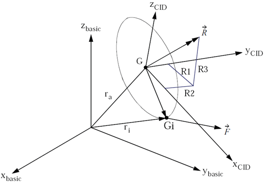
RFORCE vector at node Gi
| 2. | The RFORCE load is selected for use in a subcase by the Subcase Information entry LOAD. |
| 3. | The load vector generated by this entry can be printed using the I/O Option OLOAD. |
| 4. | For CONM1 and CONM2 entries, OptiStruct calculates the torque, due to rotation, as follows: |
![]()
Where, I is the moment of inertia.
| 5. | For mass penalization information when RFORCE is used in a Topology optimization, see Design Variables for Topology Optimization in the User’s Guide. |
| 6. | This card is represented as a loadcollector in HyperMesh. |
See Also: