| 1. | The surface segments must be orientated so that their normal vectors point towards the interior of the domain. |
| 2. | The surface must be fixed. |
| 3. | In case of an inlet condition, the condition enters particles belonging to its related part, so long as inactive particles are available for this part. The behavior of the particles belonging to the part which is related to the condition is set with respect to the condition characteristics for all particles lying on the positive side of the surface, within the distance "Dist" from the inlet surface. |
| 4. | In case of an outlet condition, the behavior of the particles belonging to the part which is related to the condition is set with respect to the condition characteristics for all particles lying on the negative side of the surface, within the distance "Dist" from the outlet surface. Such a particle is deactivated if it does not interact with any non-outgoing particle. |
| 5. | A particle deactivated by an outlet condition can be re-used by an inlet condition acting on the same part for incoming. |
| 6. | If using outlets, order = -1 is recommended in the relative SPH property. |
| 7. | In case of an outlet, the initial net must be provided up to the distance 2*h down to the outlet surface (where h is the smoothing length into the relative property). |
In case of inlet or outlet, the distance must be large enough, in order to control incoming or outgoing particles within at least a distance 2*h.
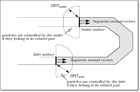
Overview of the inlet/outlet conditions organization
| 8. | The domains defined by two inlet/outlet surfaces and distances must not overlap. |
| 9. | It is recommended for both, inlets and outlets, particles to be initially defined and controlled within more than twice the smoothing length of the particles. |
| 10. | Inlet/outlet conditions option is allowed for SPMD parallel version. Parallel Arithmetic (same numerical results obtained whatever the number of processors) is not guaranteed for inlet conditions. |
| 11. | Each incoming particle belonging to the part which is related to the condition gets the same mass mp (defined into the geometrical property which is attached to the part). |
A particle belonging to this part is entered at the center of a surface segment each time t such that:
Where, Si is the area of the segment,  (t) and (t) and  (t) are the density and velocity of the incoming matier (Lines 2 and 3), and tlast was time at last incoming through this segment. (t) are the density and velocity of the incoming matier (Lines 2 and 3), and tlast was time at last incoming through this segment.
It is recommended to use a regular surface mesh.
| 12. | If no inactive particle belonging to this part is available for incoming, the program stops and you should provide a larger set of inactive particles for this part. |
| 13. | If a particle belonging to the part which is related to the condition lies on the positive side of the surface within the "Dist", its velocity is set with respect to the data given at Line 5. |
| 14. | If fct_IDr = 0, density of the incoming particles is set to:  , else , else  . . |
| 15. | If fct_IDE = 0, energy per volume unit of the incoming particles is set to Ea = FscaleE, else Ea = FscaleE* fp(t). |
| 16. | If a particle belonging to the part which is related to the condition lies on the negative side of the surface within the "Dist", its internal pressure is set with respect to the data given at Line 6. |
| 17. | If the particle does not interact with any non-outgoing particle, the particle is deactivated. |
| 18. | If fct_IDP = 0, internal pressure of the outgoing particles is set to the internal pressure of the closest particle lying above the outlet surface, else it is set to FscaleP * fP(t). |
| 19. | If a particle belonging to the part which is related to the condition lies on the negative side of the surface within the "Dist", its internal pressure is set with respect to the equation: |
| 20. | If fct_IDP = 0, pressure in the far field P is set to FscaleP, else it is set to FscaleP fP(t). is set to FscaleP, else it is set to FscaleP fP(t). |
| 21. | lc is the characteristic length, it allows to compute cutoff frequency fc as: |

| 22. | If Itype = 2, 3 or 4, the surface can be defined by a meshed surface (surf_ID > 0), by 3 nodes (node_ID1 > 0, node_ID2 > 0 and node_ID3 > 0) or by the coordinates of 3 nodes (M, M1 and M2). |
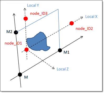
| 23. | If Itype = 2, 3 or 4 and if the surface is defined by 3 coordinates, then the surface will be fixed. If the surface is defined by a surface ID or by 3 nodes, the surface will move according to the displacement of the shell elements or nodes. |
| 24. | If Itype = 2, 3 or 4, a computation of the total mass crossing the surface is automatically performed and can be plotted using /TH/SPH_FLOW. |
|


