HyperWorks Solvers

/SECT

/SECT

Previous topic Next topic Expand/collapse all hidden text  

/SECT

Previous topic Next topic JavaScript is required for expanding text JavaScript is required for the print function  

Block Format Keyword

/SECT - Sections

Description

A section is a set of nodes and a set of elements.

Format

(1)

(2)

(3)

(4)

(5)

(6)

(7)

(8)

(9)

(10)

/SECT/sect_ID/unit_ID

sect_title

node_ID1

node_ID2

node_ID3

grnod_ID

ISAVE

Frame_ID

symbol_time

symbol_a_14

file_name

grbric_ID


grshel_ID

grtrus_ID

grbeam_ID

grsprg_ID

grtria_ID

Ninter


Iframe


Input read only if Ninter > 0

(1)

(2)

(3)

(4)

(5)

(6)

(7)

(8)

(9)

(10)

int_ID1

int_ID2

int_ID3

int_ID4

int_ID5

int_ID6

int_ID7

int_ID8

int_ID9

int_ID10

hmtoggle_plus1Flag Definition

Field

Contents

SI Unit Example

sect_ID

Section identifier

(Integer, maximum 10 digits)


unit_ID

Optional unit identifier

(Integer, maximum 10 digits)


sect_title

Section title

(Character, maximum 100 characters)


node_ID1

Node identifier N1

(Integer)


node_ID2

Node identifier N2

(Integer)


node_ID3

Node identifier N3

(Integer)


grnod_ID

Node group identifier

(Integer)


ISAVE

Saving the data flag

(Integer)

= 0: Do not save

= 1: Displacements are saved in the section cut file "file_name"

= 2: same as 1, in addition the section resultant force and moment components are saved in the section cut file.

= 100: The data contained in the section cut file "file_name" is read as input for the calculation.

= 101: same as 100, in addition the difference between section resultant force and moment between full and cut model are calculated (Comments 5 through 8).


Frame_ID

Moving frame identifier (Comment 20)

(Integer)


symbol_time

Time step for saving the data

(Real)

symbol_S_unit

symbol_a_14

Coefficient for filtering (symbol_a_14 < 1)

(Real)


file_name

Root name of the file which contains the flag output. The extension for this file is nameSC01

(Character, maximum 100 characters)


grbric_ID

Brick group identifier

(Integer)


grshel_ID

Shell group identifier

(Integer)


grtrus_ID

Truss group identifier

(Integer)


grbeam_ID

Beam group identifier

(Integer)


grsprg_ID

Spring group identifier

(Integer)


grtriag_ID

Triangle group identifier

(Integer)


Ninter

Number of interfaces

(Integer)


Iframe

Computing the skew center local skew is the skew flag defined by node_ID1, node_ID2, and node_ID3 (see figure in Comment 14)

(Integer)

The center C is given in the local skew:

= 0: the origin of the local skew (C0)

= 1: the geometrical center of the section (C1)

= 2: the CoG of the section (C2)

= 3: point o(0,0,0) is the center of the local skew


The center C is given in the global skew:

= 10: the origin of the global skew (C0)

= 11: the geometrical center of the section (C1)

= 12: the CoG of the section (C2)

= 13: point o(0,0,0) is the center of the global skew


int_ID1, int_ID2, ..., int_IDn

Optional interface identifiers, if Ninter > 0

(Integer)


hmtoggle_plus1Comments
1.Resulting forces and moments acting on these sections will be stored in the Time History file.
2.You can save force and moment in an output file. This output could be used as input for another calculation.
3.Nodes node_ID1 and node_ID2 define the local X-axis of the section.
4.Nodes node_ID1, node_ID2 and node_ID3 define the local plane XY of the section.
5.Flag ISAVE is used for saving data in the SC01 file for the cut methodology.

It is recommended to set ISAVE =0 if no cut methodology is intended, since performance may be decreased and memory for RADIOSS Engine will be increased.

6.If ISAVE = 1, displacement of section nodes are saved in the file "file_nameSC01" at a frequency symbol_trit.

If ISAVE =2, the components of resultant section force and moments are also saved in file "file_nameSC01".

7.If ISAVE = 100, displacements of section nodes are read from the file "file_nameSC01".

If ISAVE =101, the components of resultant section force and moments are also read from the file "file_nameSC01"

The displacements are filtered according to the following relations:

y+ = symbol_a_14x + (1-symbol_a_14)y

with,

clip0584  for filtering -3dB

clip0585  for filtering -6dB

Where, T is the filtering period, in general, T = 10symbol_trit.

Typical use clip0586.

8.Parameters ISAVE=1, 2, 100, and 101 are used for so-called submodeling technique. In this case a full model is run with ISAVE=1 or 2 in order to save displacement or displacement and resultant section forces/moments in file "file_nameSC01". Afterwards the cut model is created where displacement of the nodes are read from the file with ISAVE=101 or 102 option. If ISAVE=2 is used in the full model and ISAVE=101 is used in the cut model, then RADIOSS may output the difference between resultant section forces and moments in full and cut model in the section (/TH/SECTIO).
9.Moments are computed with respect to the section center defined by the parameter Iframe (see figure in Comment 14) and expressed in the local section frame.
10.Normal force is the component normal to the XY plane of the section. Tangential force is the component in the plane of the section.

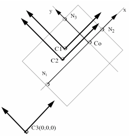
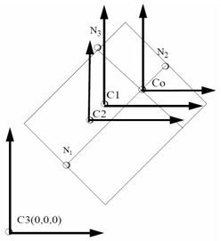
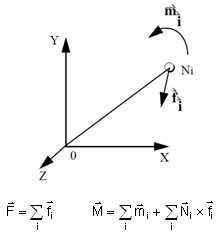
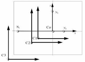
In plot file FNX, FNY, FNZ, FTX, FTY, and FTZ are respectively the components of normal and tangential forces in the global frame (see figure below for the definition of the local frame).

11.Moments calculation if Iframe = 0, 1, 2 or 3.

clip0125

12.Moments calculation if Iframe = 10, 11, 12 or 13.

clip0126

13.Forces and moments calculation.

clip0127

14.Local reference frame (Ox and Oy):

clip0128

15.The center C0 is given by the nodes: node_ID1, node_ID2 and node_ID3.
16.The center C1 is the geometric center of the section nodes:

clip0587

where, n = nodes

17.The center C2 is the center of gravity of the section nodes:

clip0588

18.The center C3 is the node with coordinates (0, 0, 0) in the global skew.
19.Frame had to be a moving frame (defined with 3 nodes).
20.If Frame_ID ≠ 0, if N1, N2, N3 equal zero, local skew of the section is built with nodes of the frame.
21.If Frame_ID ≠ 0, the set of node is created automatically by intersecting the (oXY) plane of the frame with the sets of elements.

The set of node contains nodes of intersected elements which are upside (+Z direction) and inside the (oXY) plane of the frame. The recalculated sets of elements contain elements cut by the (oXY) plane of the frame.

See Also:

Sections in User's Guide

Skew and Frame (/SKEW & /FRAME)