The Properties tab allows you to define the properties of a beam with circular, rectangular, and arbitrary cross sections.
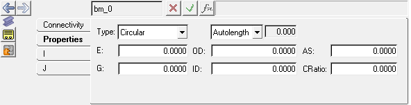
Beams panel - Properties tab
| • | If you define a circular beam, the options include E, G, OD, ID, AS, and CRatio. |
| • | If you define a rectangular beam, the options include E, G, P2Dim, P3Dim, AS2, AS3, and CRatio. |
| • | If you define an arbitrary beam, the options include E, G, Area, I11, I22, I33, AS2, AS3, and CRatio. |
Use:
|
To:
|
E
|
enter Young’s modulus of elasticity.
|
G
|
enter the shear modulus of elasticity.
|
OD
|
enter the outer diameter of the polybeam cross section.
|
ID
|
enter the inner diameter of the polybeam cross section.
|
AS
|
enter the correction factor for the shear deflection.
|
CRatio
|
enter the stiffness to damping matrix ratio. The damping matrix for the beam is computed by multiplying the stiffness matrix by the C ratio.
|
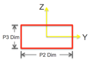
P2 Dim
|
enter the length of one of the sides of the rectangular cross section.
|
P3 Dim
|
enter the length of the other side of the rectangular cross section.
|
Area
|
enter the area of the cross section of the beam.
|
I11
|
enter the polar moment of inertia of the beam cross section.
|
I22
|
enter the area moment of inertia about the beam’s y axis.
|
I33
|
enter the area moment of inertia about the beam’s z axis.
|
AS2
|
enter the shear coefficient in the Y direction.
|
AS3
|
enter the shear coefficient in the Z direction.
|
The length of a beam can be controlled using the Length drop-down menu. When length is set to Autolen, the length of the beam is computed as the distance between the two endpoints. The text box is locked when Autolen is used. Select Length from the drop-down menu to unlock the text box and enter a beam length. The length option can be used to preload the beam.
The beam entity has coordinate systems (I and J) associated with it. By default, the X axis of the coordinate system points along the length of the beam defined by the connecting points.
For Rectangular beam, P2 Dim and P3 Dim are along the Y axis and Z axis of the beam coordinate system respectively.