|
»Click here to display Table of Contents«
|

AutoBumpStop |

|

|

|

|
|
AutoBumpStop |
|
|

|

|
|
»Click here to display Table of Contents«
|
AutoBumpStop |
|
|
|
|
|
AutoBumpStop |
|
|
|
|
The BumpStop restricts the movement of the suspension while in bump, or jounce, by applying a force between two parts.
The BumpStop force verses deflection tables are stored in an ADAMS/Car™ compatible property file. You must select a BumpStop property file to determine the BumpStop properties. Example property files are provided in the MotionView installation at:
$(ALTAIR_HOME)\hw\mdl\autoentities\properties\Bumpers-Jounce
For more information about spring property files - see the BumpStop Properties section below.
The BumpStop force can be a linear or non linear type and is computed from the force deflection table from the property file. The force contains two components:
| • | Elastic force or stiffness |
| • | Viscous force or damping |
For a linear BumpStop, the elastic force component is calculated using a third order polynomial, and for a non-linear BumpStop the elastic force component is interpolated using the Akima method.
The viscous force component, when defined in the property file, is calculated directly from the damping rate in the property file and resultant instantaneous velocity between the two bodies.
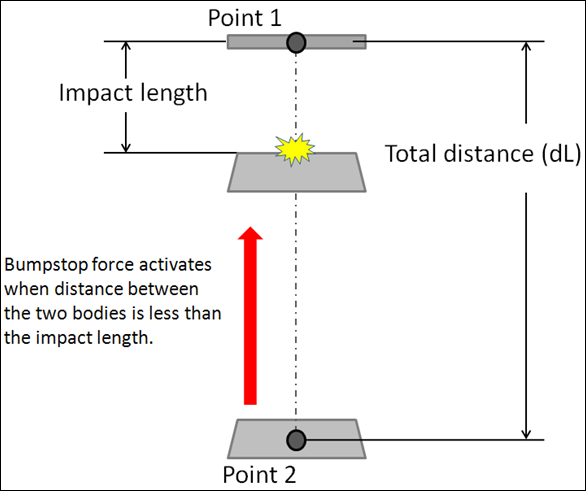
You select the two bodies between which the BumpStop force acts and two points are used to calculate the impact distance. The BumpStop force is activated when the distance between the bodies is less than a specified length. This distance is calculated based on the installation method.
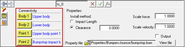
BumpStop panel
The BumpStop install method is at design position and is used to determine the distance at which the BumpStop force starts acting.
The table below summarizes the two available install methods:
Method |
Description |
|---|---|
Impact Length |
When the impact length is of value ‘L’, the BumpStop force acts when the distance between the two bodies is less than ‘L’. |
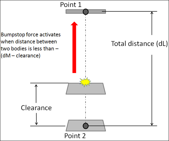
Clearance |
When the Clearance method is used, the impact distance is calculated using:
Where,
The BumpStop force activates when the distance between the two bodies is less than ‘D’. |
When the Impact Length install method is used, its value is directly used to activate the BumpStop force between the two bodies. The image below represents how the BumpStop works when using the Impact method:
|
Given a clearance value, the impact distance is calculated using the following equation.
Where,
|
When you add an AutoBumpStop Pair to your model MotionView will automatically reflect the modifications you make to the left BumpStop of the pair to the right BumpStop also, unless you choose otherwise. MotionView assumes bilateral symmetry about the global X-Z plane. However, the Symmetry option menu allows you to tell MotionView to reflect modifications from right side to the left (Right -> Left) or not to reflect modifications at all (None).
MotionView’s Symmetry feature means you only need to enter data for one side, thus saving you time. The None option does allow you to alter the left and right BumpStops independently, thus allowing you to model Asymmetric BumpStops due to manufacturing tolerances or design.
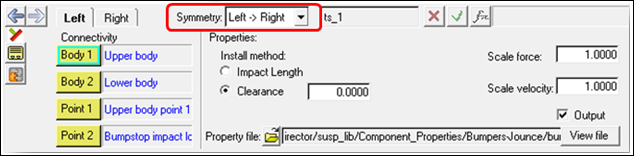
AutoBumpStop Pair Symmetry Option Menu
Options |
Description |
|---|---|
Left -> Right |
Select ‘Left -> Right’ to instruct MotionView to reflect modifications you make to the left BumpStop to the right BumpStop of the pair also. You may not modify the connectivity or properties of the right BumpStop. |
Right -> Left |
Select ‘Right -> Left’ to instruct MotionView to reflect modifications you make to the right BumpStop to the left BumpStop of the pair also. You may not modify the connectivity or properties of the left BumpStop. |
None |
Select ‘None’ to instruct MotionView not to reflect modifications you make either BumpStop of the pair. You may modify the connectivity and properties either BumpStop independently, allowing for asymmetrical connectivity or properties. |
Activating the Output check box adds an output request for the BumpStop resultant displacement, resultant velocity, and resultant force.
The resultant displacement and velocity is measured between Point 1 and Point 2 and the resultant force is measured between Body 1 and Body 2.
The table below summarizes the output channels in the MotionSolve .mrf file:
TYPE |
Component |
Quantity |
|---|---|---|
REQSUB |
RESULT(2) |
Distance between Point 1 and Point 2 on the BumpStop. |
|
RESULT(3) |
Rate-of-change-of-displacement between Point 1 and Point 2. |
|
RESULT(4) |
BumpStop force. |
|
RESULT(6) |
Global X direction cosine of BumpStop. |
|
RESULT(7) |
Global Y direction cosine of BumpStop. |
|
RESULT(8) |
Global Z direction cosine of BumpStop. |
The BumpStop properties are stored in a TeimOrbit format text file. When you resolve the property file field to a BumpStop property file and submit the model to the solver, the solver reads the BumpStop property file for use during simulation. If the units in the property file differ from the model units, the solver internally converts the BumpStop properties to the model units. The properties file remains unchanged. The BumpStop properties file contains header, units, and curve blocks. The units block specifies the length, mass, force, time, and angle units employed in the file. The curve block holds a table of displacement against force values for the elastic force component and optionally a velocity against force values for the viscous force component. An example BumpStop property file is shown below: $--------------------------------------------------------------------HEADER [HEADER] FILE_TYPE = 'bum' FILE_VERSION = 4.0 FILE_FORMAT = 'ASCII'$ ---------------------------------------------------------------------UNITS [UNITS] LENGTH = 'mm' ANGLE = 'degrees' FORCE = 'newton' MASS = 'kg' TIME = 'second' $---------------------------------------------------------------------CURVE [CURVE] { disp force} 0.0 0.0 2.0 1.0 4.0 2.0 6.0 3.0 8.0 4.0 10.0 5.0 20.0 6.0 30.0 7.0 40.0 8.0 50.0 9.0 |