|
»Click here to display Table of Contents«
|

AutoDamper |

|

|

|

|
|
AutoDamper |
|
|
|

|
|
»Click here to display Table of Contents«
|
AutoDamper |
|
|
|
|
|
AutoDamper |
|
|
|
|
The AutoDamper is a force-velocity model designed to easily simulate a shock absorber used in ground vehicles. The AutoDamper entity reads force-velocity data from a file written in the TeimOrbit format.
Some advantages of the AutoDamper element include the following:
| • | The damper properties are defined in a readable ASCII format file. |
| • | The damper file can be referenced multiple times in the model (for symmetric dampers and for dampers that are used in more than one location). |
| • | The data file format is used in other MBD codes, such as SIMPACK and ADAMS. |
| • | The math that defines the Force-velocity relationship is contained in a subroutine, instead of in the user interface. |
The Autobush uses a Force_Scalar_Twobody XML statement in the MotionSolve deck, along with a subroutine to calculate the force in the bushing.
The MotionView graphical user interface is shown below. The function of each section of the interface is also described in the image below:
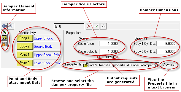
Select the points and bodies using the Motionview Project Browser. The AutoDamper generates a damping force that acts on a line between points 1 and 2. Point 1 moves with Body 1 and Point 2 moves with Body 2.
The Property file browser allows you to browse and select a damper property file. The file should be in the TeimOrbit format as shown in the example below. Example files are available in the Hyperworks installation.
The View file button brings up a browser view of the property file. The file can be viewed, however it cannot be edited or saved.
If the Output box is checked, an output request is written to the output file.
The Scale force and Scale velocity numbers apply a scale factor to the damper curves. They are typically used to convert data from one unit set to another. Factors are supplied for force and velocity to simplify the scale input.
The Body-1 Cyl. Dia and Body-2 Cyl Dia fields are used to define the dimensions of the damper.
Click on the yellow icon to see the internal number and naming scheme for the damper, and also to save data about the damper.
A Damper Graphic appears when an AutoDamper is added using the graphical user interface. The graphic includes two cylinders (and is shown in the image below).
The gray cylinder is attached to Body 1 and will move with that body. The red graphic is associated with Body 2 and will move with Body 2. Graphic sizes are calculated automatically and can be modified by expert users by editing the damper system definition.
The blue and pink arrows shown in the picture below are the MotionView Implicit graphics associated with the Force created by the AutoDamper:
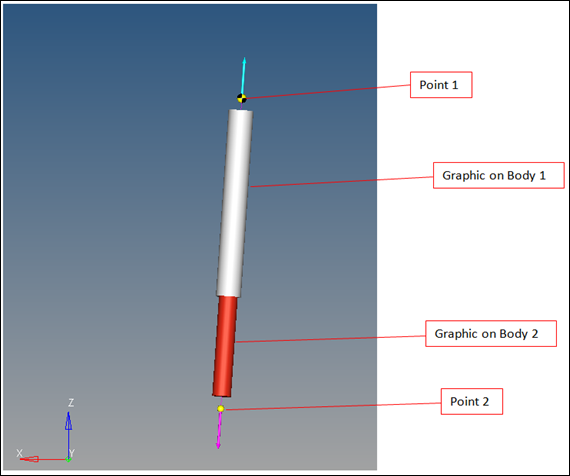
Autodamper Graphic
A sample TeimOrbit format damper text file is shown below. Enter the damper curve data in ascending order.
$----------------------------------------------HEADER
[HEADER]
FILE_TYPE = 'dpr'
FILE_VERSION = 4.0
FILE_FORMAT = 'ASCII'
$----------------------------------------------UNITS
[UNITS]
LENGTH = 'mm'
ANGLE = 'degrees'
FORCE = 'newton'
MASS = 'kg'
TIME = 'second'
$----------------------------------------------CURVE
[CURVE]
{ vel force}
-4916.935 -8.889
-1000.0 -3.0
-500.0 -1.5
-250.0 -0.75
-100.0 -0.3
0.0 0.0
100.0 0.3
250.0 0.75
500.0 1.5
1000.0 3.0
4914.298 9.0416