|
»Click here to display Table of Contents«
|

Datasets |

|

|

|

|
|
Datasets |
|
|
|

|
|
»Click here to display Table of Contents«
|
Datasets |
|
|
|
|
|
Datasets |
|
|
|
|
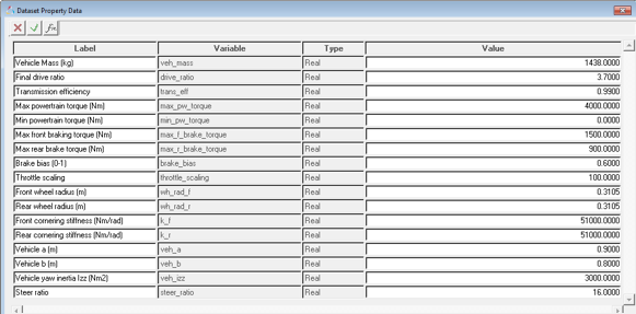
Some of the driver controllers (Feedforward controllers, gear shift controller) need vehicle information. This information can be provided using datasets. If these controllers are not used, you do not need to populate this dataset. The graphical user interface automatically populates these datasets.
Parameter |
Type |
Range |
Comments |
|---|---|---|---|
Vehicle Mass |
Real |
Value>0 |
|
Final drive ratio |
Real |
Value>0 |
Coupler ratio between drive coupler output and input shafts. Note that drive ratio is 3.7 in case of default RWD model and 1 in case of default FWD model. This value is not parameterized. |
Transmission efficiency |
Real |
Value>0 |
Input omega/(output omega*Drive ratio). |
Drive type |
Option |
Value = FWD or RWD |
Four wheel drive not allowed for advanced driver. |
Max. powertrain torque |
Real |
Value > 0 |
Torque produced by the powertrain at the input shaft of the differential at 100% throttle. *Required only for vehicle models without CSE powertrain. Driver can directly query CSE powertrain. |
Min. Powertrain torque |
Real |
|
Torque produced by the powertrain at the input shaft of the differential at 0% throttle. *Required only for vehicle models without CSE powertrain. Driver can directly query CSE powertrain. |
Maximum front braking torque |
Real |
value>0 |
Maximum braking torque on front axle at 100. |
Maximum rear braking torque |
Real |
Value>0 |
Maximum braking torque on rear axle. |
Brake bias |
Real |
0<Value<1 |
Front to Rear. 0 is 100% front, 1 is 100% rear. |
Front wheel radius |
Real |
Value>0 |
Loaded radius |
Rear wheel radius |
Real |
Value >0 |
Loaded radius |
Front cornering stiffness |
Real |
Value>0 |
|
Rear cornering stiffness |
Real |
Value>0 |
|
Vehicle a |
Real |
Value>0 |
X component (Vehicle SAE system) of the distance from vehicle front axle to vehicle CG. |
Vehicle b |
Real |
Value>0 |
(Wheel base - vehicle a) |
Vehicle yaw inertia |
Real |
Value>0 |
|
Steer ratio |
Real |
Value>0 |
Ratio of steering wheel input to tire motion (toe). |
An Analysis settings dataset is required for user to give initial condition of the vehicle, simulation time and address of the Altair Driver file. This interface is a temporary data set and in the future these settings would go to Altair Driver file. The only thing that this data set would contain is the address of the Altair Driver file.
Parameter |
Type |
Range |
Comments |
|---|---|---|---|
Altair Driver file |
File |
|
Address of the file path |
A signal dimensions dataset is required to pass driver the information like Labels, ID, and dimensions of the end signals.
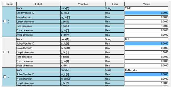
Use Case:
$Example ADF end conditions block
(END_CONDITIONS)
{SIGNAL GROUP ABS OPERATOR VALUE TOLERANCE WATCH_TIME}
LONG_VEL 0 Y SS 0.0 0.0001 1.50
ROLL_ANGLE 1 Y SS 0.0 0.0001 1.50
PITCH_ANGLE 2 Y SS 0.0 0.0001 1.50
YAW_RATE 3 Y SS 0.0 0.0001 1.50
CG_Z 4 Y SS 0.0 0.0001 1.50
$------------------------------------------------------------------------------------------------------------------
Using this block in ADF and signals dimension dataset, Driver will know the appropriate conversion factors for each and every value.
The scripted driver works on the CSE architecture. A graphical user interface for CSE architecture is not supported, therefore one has to change MDL statements in order to make any changes.
MDL Statements |
|
|---|---|
*GeneralStateEquation( gse_advanced_driver, "CSE Advanced Driver", 6, sa_u_advanced_driver, , ) |
|
gse_advanced_driver |
Variable name of the driver cse. |
“CSE Advanced Driver” |
Label |
6 |
Number of outputs. |
sa_u_advanced_driver |
Solver array with input signals. |
|
Driver resizes the state array and sets initial conditions of the states internally. Hence, the state IC array should not be provided. |
*SetGeneralStateEquation( gse_advanced_driver, USER, `USER({sa_par0.idstring},1)` ) |
|
USER |
Indicates that Motionsolve should look outside its dll’s for the entry point. |
USER({sa_par.idstring}) |
Function call with par[0] = Array ID with vehicle parameters |
*SetContinuousStates( gse_advanced_driver, 1 ) |
|
1 |
The number of states are by default set to 1. |
*SetLocalUserDLL( gse_advanced_driver, "msautoutils" ) |
|
Msautoutils |
Looks for this dll first in the current directory and then in Motionsolve installation. |
*SetLocalUserFuncname( gse_advanced_driver, "SCRIPT_DRIVER" ) |
|
SCRIPT_DRIVER |
Entry point function name. |
Steering wheel motion |
Driver computes the required steering angle and applies motion to the steering wheel joint. |
Front and rear wheel motion |
Required to lock the wheels during static simulation and lock the wheels. |
Differential motion |
Required to lock the differential during static. |
These solver arrays are parameterized to data sets or attachments. You do not need to fill/edit them.
Mass Info Array |
0 Reserved 1 Mass of the vehicle |
Brake Info Array |
0 Reserved 1 Max front braking torque 2 Max rear braking torque 3 Brake bias 4 Reserved 5 Reserved |
Tire Info Array |
0 Reserved 1 Front wheel loaded radius 2 Rear wheel loaded radius 3 1 if FWD 2 if RWD 4 Reserved 5 Reserved |
Drag Info Array |
0 Reserved 1 Air density 2 Drag coefficient 3 Frontal area 4 Reserved 5 reserved |
Driver Info |
0 Reserved 1 Altair Driver file path string ID 2 Solver array signals channel ID 3 Reserved 4 Reserved |
Drive Train Info Array |
0 Reserved 1 Final drive ratio 2 Transmission efficiency 3 Number of gears 4 Gear ratio 1 5 Gear ratio 2 6 Gear ratio 3 ….. 14 Gear ratio 10
*If gear index, i > Number of gears, N Gear Ratio [i] = Gear Ratio[N] |
Bicycle Model Info Array |
0 Reserved 1 Front cornering stiffness 2 Rear cornering stiffness 3 Vehicle a 4 Vehicle b 5 Yaw inertia 6 Steer ratio 7 Reserved 8 Reserved |
Vehicle Parameters Array |
0 Reserved 1 Mass info array ID 2 Brake info array ID 3 Drivetrain info array ID 4 Drag info array ID 5 Tire info array ID 6 0 7 Bicycle model array ID 8 Driver info array ID 9 Reserved 10 Reserved |
Input Signal Array |
0 Time 1 Longitudinal displacement 2 Lateral displacement 3 Vehicle heading angle 4 Vehicle longitudinal velocity 5 Vehicle lateral velocity 6 Yaw rate 7 Vehicle longitudinal acceleration 8 Vehicle lateral acceleration 9 Engine speed 11 Distance travelled
Signal channel 12 Signal 0 13 Signal 1 14 Signal 2 15 Signal 3 16 Signal 4 |
Control Entity Array List of motion ID’s and Joint ID’s passed to driver for deactivation after running static analysis |
0 Reserved 1 Steering wheel motion ID 2 Front left wheel motion ID 3 Front right wheel motion ID 4 Rear left wheel motion ID 5 Rear right wheel motion ID 6 Differential motion ID *Required only if there is NO cse powertrain 7 J Prim 1 ID 8 J Prim 2 ID 9 sv_steer_angle ID |
Steer |
Driver steer output -ARYVAL ( {driver_output_array_id }, 1 ) |
Throttle |
Driver throttle output ARYVAL ( {driver_output_array_id }, 2 ) |
Brake |
Driver brake output ARYVAL ( {driver_output_array_id }, 3 ) |
Gear |
Driver gear output ARYVAL ( {driver_output_array_id }, 4 ) |
Clutch |
Driver clutch output ARYVAL ( {driver_output_array_id }, 5 ) |
Distance traveled by the vehicle |
DIF ( {diff_dis_travel.id} ) |
Longitudinal velocity wrt to gyro |
-VX ( <Gyro fixed marker> , <Ground body CM marker> , < Gyro fixed marker > ) |
Lateral velocity wrt gyro |
VY ( <Gyro fixed marker> , <Ground body CM marker> , < Gyro fixed marker > ) |
Yaw rate wrt gyro |
WZ ( <Gyro fixed marker> , <Ground body CM marker> , < Gyro fixed marker > ) |
Longitudinal acceleration wrt gyro |
-ACCX( <Gyro fixed marker> , <Ground body CM marker> , < Gyro fixed marker > ) |
Lateral acceleration wrt gyro |
-ACCY( <Gyro fixed marker> , <Ground body CM marker> , < Gyro fixed marker > ) |
Engine speed |
Engine speed attachment |
Longitudinal displacement |
DX ( <Vehicle Body>) |
Lateral displacement |
DY ( <Vehicle Body>) |
Vehicle heading angle |
AZ ( <Vehicle Body>) |
Simulation time |
TIME |
Roll Angle |
AX(<Vehicle Body>) |
Pitch Angle |
AY(<Vehicle Body>) |
Roll Rate |
WX(<Vehicle Body>, <Ground Body>, <Vehicle Body>) |
Pitch Rate |
WY(<Vehicle Body>, <Ground Body>, <Vehicle Body>) |
<ResOutput plt_file = "TRUE" /> |
PLT file is generated at the end of the simulation. |
<DebugOutput Switch_On = "FALSE" Stat_Anim = "FALSE" /> |
Writes out states of each and every component in the model. Default = ‘FALSE’ Slows down the simulation speed if switched on. |
<UserProgramControl usrsub_param_string = "user(6454, {sys_tires.m_road_ref_frnt.l.id}, {advanced_driver.sa_deact_entities.id})" usrsub_dll_name = "msautoutils" usrsub_fnc_name = "RUN_DRIVER_EVENT" /> |
CONSUB call to simulate transient and deactivate all the motions and joints after that. |
Maneuver switch |
Switch to end one maneuver and start next maneuver. Sensor uses a sensor subroutine to monitor the signals and end conditions associated with the signal to actuate the switch. |