|
»Click here to display Table of Contents«
|

Assembly |

|

|

|

|
|
Assembly |
|
|
|

|
|
»Click here to display Table of Contents«
|
Assembly |
|
|
|
|
|
Assembly |
|
|
|
|
MotionView had the ability to create assemblies since its inception. These assemblies are in form of systems and sub-systems and can be created interactively or through a text editor using the Systems container entity. Such a system could contain any type of modeling entities, a set of bodies, joints, bushings etc. The system definition can then be saved and reused by loading (importing) it individually. A set of system definitions can also be saved into library and the model building can be automated using the Assembly Wizard.
While systems have several other advantages, they also have a couple of limitations:
| • | When the system definition is imported, the definition is copied into the model, thus saving them inline into the model. Any further modification to the system definition within the model does not update the original definition upon model save. This makes sharing and collaboration difficult. |
| • | Data (corresponding to the system definition) cannot be saved and shared separately. |
Beginning in version 11.0.120, a new container entity called "Assembly" is being introduced. The assembly is an extended version of systems which can overcome the above limitations. This method keeps definition and data in external files for each assembly. The assembly references a data file containing data and in turn, each data file references an associated definition file containing the definition.
The benefit of the new method is that when data or topology is modified within MotionView and the model saved, the data and topology save back to the original set of files that were used. If an assembly is modified separately in one model, and saved to the original data and definition files, the modifications are affected into a different model that uses the same sub-assembly.
For example, a landing gear assembly is used in an aircraft assembly. The landing gear system can be studied separately in a model that contains the landing gear assembly only. Any change made during this study to the landing gear is saved in its corresponding data/definition files. These changes become effective into a model of aircraft assembly also, as it uses the same data and definition files for the landing gear assembly.
In addition, two different landing gear assemblies in the aircraft assembly can refer to a common definition file, if they have the same topologies. In this case, the data file for each landing gear assembly shares a definition file.
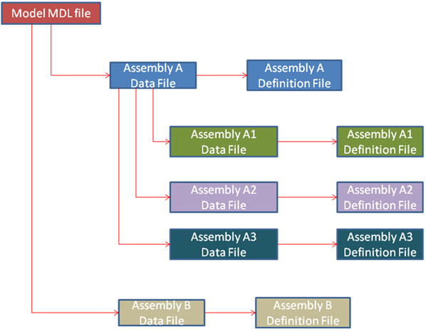
The assembly hierarchy can be of unlimited depth, and the MDL syntax is consistent and independent of which level in the hierarchy that it is used. The figure below shows that the model can have one (or more) assemblies directly off of the root of the model tree. Each of these assembly points to an associated data file. In addition, each of these assembly data files references a definition file.
An assembly has three primary elements:
| • | Assembly Placeholder |
| • | Data File |
| • | Definition File |
As the name suggests, an assembly placeholder is a topological element that can hold an assembly into it. An assembly placeholder can be thought of as a null or empty assembly. Specifying a data and definition file to the placeholder fills it with an assembly that could contain any other type of modeling entities. The assembly placeholder information goes into the definition file.
The data file holds data related to the assembly and contains the following information:
| • | Definition file used. |
| • | Data corresponding to entities defined in the definition file. |
The definition file holds the primary definition for the assembly. The assembly definition is contained within *DefineAssembly() block. It contains the topological statements for the entities within the assembly and can also hold *Set statements (considered as default data). Refer to the Data and Definition section of the MDL Model Statements topic to learn more on why *Set statements are part of the definition.
The definition file can also contain *Define blocks belonging to definition based entities such as Systems, DataSets, Forms and Templates that are used in the assembly.
The assembly type is the topological type identifier specified for an assembly definition. It is used to ensure compatibility when selecting an assembly into an assembly placeholder or reselecting a previously populated assembly.
The assembly placeholder has a corresponding attribute called “Selection Type”. This attribute can be specified to restrict the type of assembly that can go into the placeholder. For example, if an assembly placeholder has a Selection Type “StrutAssembly”, only such assemblies can be specified whose definition contains the Assembly Type “StrutAssembly”.
This type follows the same naming rules as a variable or definition name (uppercase or lowercase letters, numbers and underscores, must start with a letter).
The below image demonstrates the above mentioned structure with the required set of MDL blocks, statements and associated definition and data files for a model with an assembly and a child assembly (the exact syntax and content have been omitted for sake of clarification):
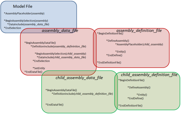
The *AssemblyPlaceholder statement creates an assembly placeholder under the parent container (Assembly or Model) which is a null assembly. The placeholder refers to a *BeginAssemblySelection block containing a *DataInclude statement that refers to an assembly data file, thereby instantiating the assembly into the placeholder.
The data file would contain a *BeginAssemblyDataFile block which in turn holds a *DefinitionInclude statement that refers to an assembly definition file. The definition file contains the definition of entities within a *DefineAssembly block. It can also contain other *Define blocks that are used to instantiate definition based entities like Systems, Datasets, Templates, etc. All of the *DefineXXX blocks reside under *BeginDefinitionFile block.
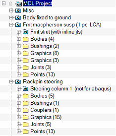
An example model of a single cylinder engine mechanism is available under ~hw_install/demos/mv_hv_hg/modeling/mdl_examples/container_entities/assembly which demonstrates the assembly concept:
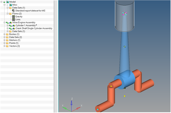
This model is made of an higher level assembly called “Inline Engine Assembly” with child assemblies “Cylinder 1 Assembly” and “Crank Shaft Single Cylinder Assembly”.
The images below show the methodology of defining this assembly using the MDL language. The Model mdl file has an *AssemblyPlaceholder statement (assem_eng_inline) that refers to a *BeginAssemblySelection block. This block contains a *DataInclude statement that refers to the data file for the Inline Engine Assembly (data_inline_engine.mdl).
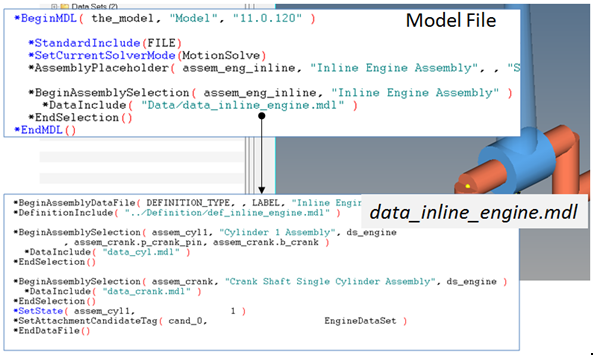
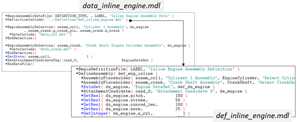
The data file has a parent block of *BeginAssemblyDataFile. This data file refers to the definition file def_inline_engine.mdl through the *DefinintionInclude statement. The definition file holds the definition for this top level assembly that contains assembly placeholder statements for “Cylinder 1 Assembly” and “Crank Shaft Assembly” within the *DefineAssembly block. The definition file also contains a dataset definition. The corresponding BeginAssemblySelection blocks are in the data file. These blocks refer to the data files for the cylinder assembly and crank shaft assembly respectively (data_cyl.mdl and data_crank.mdl). The data file also contains data related to entities within the definition.
The cylinder and crankshaft assembly data and definition file structures are similar to the parent assembly structure as explained above. These child assemblies also take attachments as can be seen in the example below:
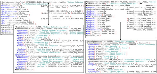
Cylinder Assembly and Crankshaft assembly – data and definition files
| Note | The above example has two levels. A similar assembly can be created with "N" level deep hierarchy. |
An assembly can be added into a model into the top level Model, another assembly, or an analysis of external type in the model. Assemblies cannot be added to Inline type systems or analyses.
There are three different ways of adding an assembly based on whether or not the data and definition files exist:
| • | New Data and Definition file |
| • | New Data and existing Definition file |
| • | Existing Data file |
Use this method to create an assembly from scratch. At the end of the assembly addition process, a blank instance of the assembly is available to which entities can be added. The topology statements will be saved to the specified new definition file and the (property) *Set statements will be saved to the data file.
Use this method to add an existing assembly definition. At the end of the assembly addition process, the assembly contained in the definition file will be loaded into MotionView with the default properties in the definition file. Any change to the properties of entities would be saved to the new data file. For new entities that are added further, the topology statement would be saved to the definition file, but the properties would be saved to the data file.
Use this method to add an assembly which uses an existing data (and thereby existing definition, as data file references a definition file). At the end of the assembly addition process, the assembly contained in the definition file will be loaded into MotionView with the properties from the data file. Any change to the properties of entities would be saved to the data file. For new entities that are added further, the topology statement would be saved to the definition file, but the properties would be saved to the data file.
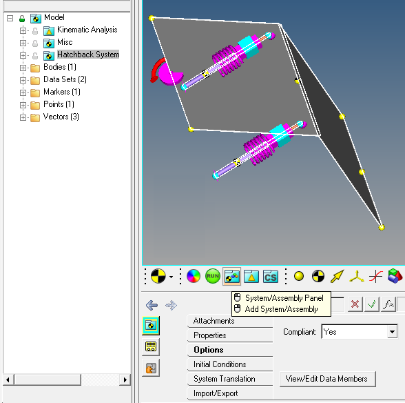
An assembly can be selected and its properties viewed using the System/Assembly button from the from the Container Entity toolbar:
| • | Left click on the System/Assembly button to filter the graphic selections to system or assemblies. Clicking on the graphic in the graphics area would then select the system or assembly. |
| • | Right click on the System/Assembly button to add a system or assembly. See the System/Assembly Panel topic to learn more about adding a system or an assembly. |