|
»Click here to display Table of Contents«
|

NLFE Stabar |

|

|

|

|
|
NLFE Stabar |
|
|
|

|
|
»Click here to display Table of Contents«
|
NLFE Stabar |
|
|
|
|
|
NLFE Stabar |
|
|
|
|
A stabar, also known as anti-roll bar, is a member that is used in automobile suspensions to increase roll stiffness. This helps in reducing the body roll of a vehicle during cornering or when the vehicle traverses on road undulations.
An NLFE Stabar system is a MotionView system definition that can be used to represent a stabar as a non-linear finite element body assembled with accessories like drop links and attachment joints.
A Stabar can be added in MotionView using the toolbar icon ![]() .
.
A stabar needs the following entities to be present in the model:
| 1. | A vehicle body on which the stabar is mounted. |
| 2. | Suspension components like control arms/knuckles, etc. to which the stabar end drop-links are attached. |
| 3. | Optionally, a pair of points for the drop-link attachment to the suspension components mentioned above. |
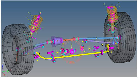
A typical suspension is shown below:
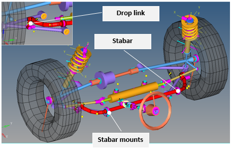
NLFE Stabar (shown in red) in a front suspension
Click on the NLFE Stabar Subsystem toolbar icon ![]() to invoke the Add an NLFEStabar Subsytem dialog.
to invoke the Add an NLFEStabar Subsytem dialog.
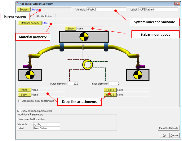
Add an NLFEStabar Subsystem dialog – Properties tab
Outer diameter |
Outer diameter of the stabar tube. |
Inner diameter |
Inner diameter of the stabar tube. |
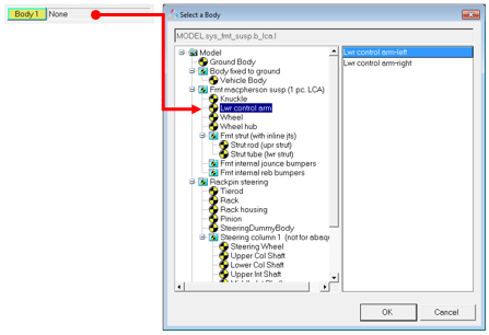
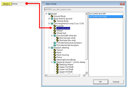
Body and Point attachments can be resolved by double clicking on the respective collectors to bring up the model tree. The sequence that completes the entries is as shown below:
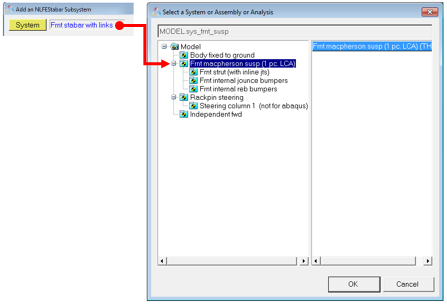
| 1. | Select the System in which the stabar needs to be created. |
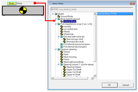
| 2. | Select the stabar mount body. |
| 3. | Select the attaching points and bodies on either side for drop link. |

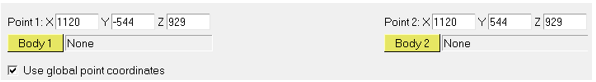
Select Point 1 and Point 2 if available in the model. If not, activate the Use global point coordinates check box and key in the coordinates where points for attachments are to be created.
| 4. | Enter Outer diameter and Inner diameter values for the stabar tube. |
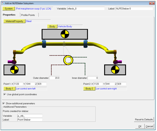
NLFE Stabar – Properties tab
| 5. | Next, the profile of the stabar needs to be defined using a sequence of points. Click on the Profile Points tab. The sequence of operation to complete the profile selection is as shown below. The profile points is provide in the form of a table of coordinate values. The values in the table can be manually keyed in or a .csv fie can be used to import the values. |
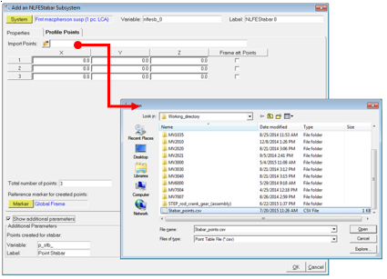
| 6. | Select a Reference Marker in which the profile points are defined. The default is Global Frame. |
| 7. | Among the profile points defined, select two points as locations to attach the stabar to the mount body (frame) using the check box in the column at the right. |
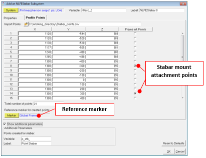
NLFE Stabar – Profile Points tab
| 8. | Click OK. |
A system is created for the Stabar in the selected parent system.
NLFE Stabar in a vehicle suspension
| Note | If at any point you want to return to default settings, simply click on the Reset to Defaults button. |
The Stabar system that is created has the following architecture:
Body |
A NLFE Body entity for the stabar is created using the profile points. |
DataSet |
A dataset where editable values are populated. After the creation of the stabar, you can change the outer diameter and inner diameter from this dataset. |
Points |
The points that define the stabar profile are created. |
Graphics |
Graphics are created for the joints for visualization. |
Joints |
Compliant Joints are created to define connections between Stabar – Frame – Drop link – Suspension components. |
Outputs |
Output requests are created to measure stabar and drop link forces. |
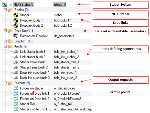
Stabar system definition and entities within
An NLFE Stabar is similar to a flexible body. You can visualize the contours of an NLFE stabar just like a CMS flex body. To visualize stress for example:
| 1. | Load the result H3D file in HyperView. |
| 2. | Go to Contour panel using the toolbar icon |
| 3. | Select the Result type: NLFE Stress (t). |
| 4. | Select Averaging method: as needed. |
| 5. | Click Apply. |
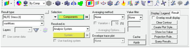
NLFE Stabar contour visualization
A testrig for stabar is provided in the install at the location: <installation_directory>\utility\mv_hv_hg\mbd\nlfe. This test rig can be used to exercise a stabar and plot its characteristics. To use the test rig, follow the steps below:
| 1. | Load the test rig model MDL file testrig_stabar.mdl in MotionView. |
| 2. | Build the NLFE stabar as explained above. |
| 3. | Solve the model in MotionSolve from the Run panel. |
| 4. | From Analysis menu, click View Reports. |
| 5. | A Stabar Test report should be available as an entry. Select it and click OK. |
| 6. | A couple of pages are loaded with animation and plots. The second page of this report has the plot of Stabar moment versus Roll angle measured at stabar ends. The slop of this plot gives the Stabar roll stiffness. |
| 7. | To view the slope, select the second window and click on the Coordinate Info button |
| 8. | Click on any point on the curve to view the Slope in the panel area. This value indicates the Stabar roll stiffness. |
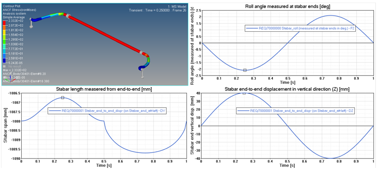
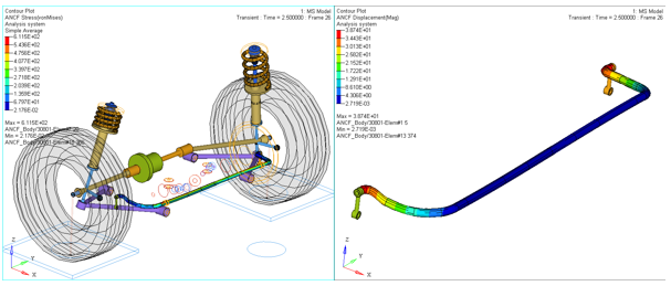
Report Page 1
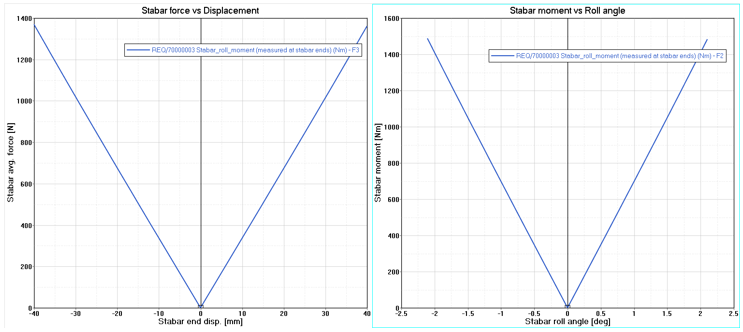
Report Page 2
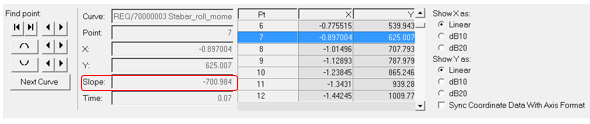
Slope of the curve at selected point