In this tutorial, you will learn how to:
| • | use an FEM file to create a flexible body file. |
| • | use body data to create a rigid body model. |
| • | make the door flexible and use the flexbody file created in the model. |
| • | set up a door closure simulation. |
Note
|
Copy the files metro_door.fem and car_body_graphics.hm, located in the mbd_modeling\flexbodies folder, to your <Working directory>.
|
Step 1: Review of a finite element model for the flexible door.
In this step, we will review the contents of the finite element (FE) model, which is the starting point for creating a flexible body.
| 1. | Import the model metro_door.fem in HyperMesh. |
| 2. | Click the Model Browser on the left of the graphics area and expand the model tree to review all components, properties, and materials of the model. |
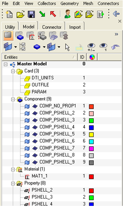
| 3. | The FEM model should have the following attributes: |
| • | A decent, quality mesh on all components. |
| • | The Section properties are assigned to all components. |
| • | All components refer to appropriate materials. |
| 4. | Identify the interface nodes of the flexible body. Please check the following nodes by ID: 9751, 9750, 10090. |
| 5. | Export the FEM as metro_door_flex.fem for Flexbody Generation. |
Step 2: Generating the flexbody using Flex Prep
In this step, we will use the FEM file created in Step 1 and use Flex Prep to generate a flexible body H3D file. A pre-requisite for going through this step of the tutorial is an understanding of Flex Prep as described in the tutorial: MV-2010: Flexbody Generation using Flexprep and Optistruct.
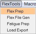
| 1. | In MotionView, from the FlexTools menu, select Flex Prep. The FlexBodyPrep dialog is displayed. |
| 2. | Once the FlexBodyPrep dialog is displayed, enter the following information in the FlexBodyPrep dialog to generate the flexbody for building the door closure model. |
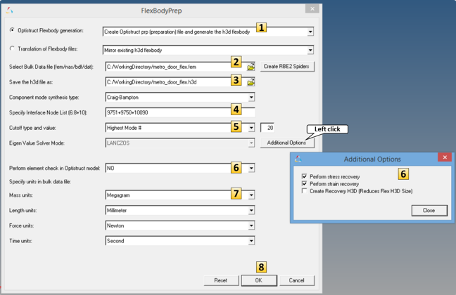
FlexPrep utility with data
| 3. | See the image above where the entries and options on the FlexBodyPrep dialog are labeled with numbers. |
| 4. | For #2, Select Bulk Data file (fem/nas/bdf/dat):, specify the input file metro_door_flex.fem generated in Step 1. |
| 5. | For #3, Save the h3d file as:, specify the output H3D file as metro_door_flex.h3d. |
| 6. | For #4, Specify Interface Node List, specify the interface node numbers as: 9751+9750+10090. |
| 7. | For #5, Cutoff type and value: select Highest Mode # and enter 20. |
| 8. | For #6, activate both Perform stress recovery and Perform strain recovery, and select No for Perform element check in Optistruct model. |
| 9. | For Mass units, select Megagram. |
| 10. | Click OK to start the flexbody generation. |
| 11. | The flexbody H3D file is generated in the selected folder with the name metro_door_flex.h3d. |
Step 3: Creating the MBD model of the car door.
In this step, you will create the MBD model of the car door, after which the door closure simulation can be performed.
For this model, use the following units for length, mass, force, and time, respectively: millimeter, megagram, Newton, second.
Model Units
| 1. | From the Forms panel,  , change the Mass units from the default Kilogram to Megagram. , change the Mass units from the default Kilogram to Megagram. |
Points
For building this model, a total of six points need to be created.
| 1. | From the Project Browser right-click Model and select Add Reference Entity > Point (or right click on Points icon,  , from the toolbar. Add the points as shown in the table below. , from the toolbar. Add the points as shown in the table below. |
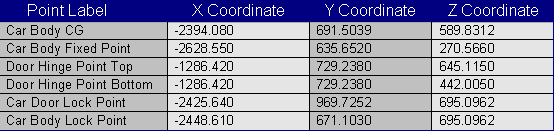
Table 1 – Points required for the model
Bodies
In this model, there are two bodies: one body to represent the car and another to represent the flexible door.
| 1. | From the Project Browser, right-click Model and select Add Reference Entity > Body (or right-click the Bodies icon,  , from the toolbar. Add a body and label it Car Body. , from the toolbar. Add a body and label it Car Body. |
| 2. | Specify the center of mass of the body as the point Car Body CG from the CM Coordinates tab. |
| 3. | Click the Properties tab of the Car Body and enter the mass and inertia properties values as shown in Table 2 below. |

Table 2 – Mass and inertia properties of the car body
| 4. | Add another body and label it Car Door. |
| 5. | From the Properties tab, click the Deformable check box. |
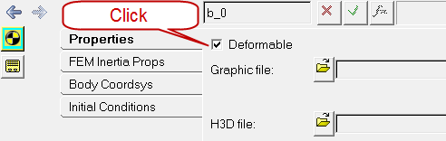
| 6. | Browse and specify the metro_door_flex.h3d file as the Graphic file: and H3D file: of the Door Body. Use the flexbody file generated in Step 2 above. |
Graphics
After Point 6 above, we see that the Door Body has a graphical representation, but Car Body is still not graphically represented. Let’s add a File Graphic to the Car Body so that visualization of the model becomes more meaningful.
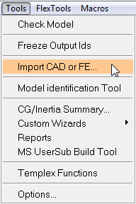
| 1. | From the Tools menu, select Import CAD or FE. |
| 2. | From the Input File drop-down menu, select HyperMesh. Use the file browser to select the HyperMesh file car_body_graphics.hm. The Output Graphic File field is automatically populated. |
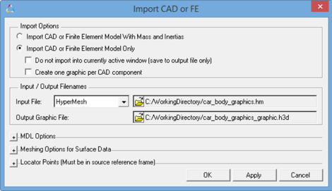
| 3. | Click OK. The HyperMesh file is converted to H3D and imported into the MotionView window. |
| 4. | From the Graphics panel,  , click the graphic just now added. , click the graphic just now added. |
| 5. | From the Connectivity tab, double-click the Body button and pick Car Body as the body. This will associate the selected graphic with the Car Body. |
Joints
For this body, we will need to add a total of four constraints/joints. One of these joints will need to be added using the XML Template.
| 1. | From the Project Browser, right-click Model and select Add Constraint > Joint (or right-click the Joints icon,  , from the toolbar). Add joints as specified in the table below. , from the toolbar). Add joints as specified in the table below. |

Table 3 – List of the joints to be created and their topology
Once the joints are specified and since there is a flexible body in the model, the interface nodes of the flexible body have to be associated with corresponding joint markers.
| 2. | From the Bodies panel, select Car Door. |
| 3. | From the Properties tab, click the Nodes… button. |
| 4. | From the Nodes dialogue, click Find All to find the interface node numbers and to resolve them with the respective connection markers. |
Initial Conditions
In this simulation, we will have body initial velocity as the primary motion input to the model.
| 1. | From the Project Browser, select the Door Body from the filter on the left. |
| 2. | Click the Initial Conditions tab. |
| 3. | Activate WZ and specify a value of 5.0 for the same. This will be the magnitude of the initial angular velocity about the global Z axis that will be applied to the Door Body. |
| 4. | Do a test simulation to check how the model behaves with just the initial velocity and the constraints. |
Markers
To represent the locking mechanism of the car door, we will use a sensor activated fixed joint between the Car Body and the Door Body that initially is deactivated. The fixed joint will need to be created using XML templates since the MotionView interface allows joints to be created using bodies and points. In this case, we need to create the joint between two initially non-coincident markers.
| 1. | From the Project Browser, right-click Model and select Add Reference Entity > Marker (or right-click the Marker icon,  , from the toolbar. Add two markers as specified in the table below. , from the toolbar. Add two markers as specified in the table below. |
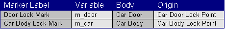
Table 4 – List of markers to be created and their topology
| 2. | Once the markers are created, repeat steps 2-4 under Joints above to resolve the node connections of Car Door Body with the maker Door Lock Mark. |
Sensor
In this model, we will use an Event Sensor to detect the closing of the door. At the instance of the event detection, the fixed joint between the door and the car body is activated to simulate the actual locking mechanism.
| 1. | From the Project Browser, right-click Model and select Add General MDL Entity > Sensor (or right-click the Sensor icon,  , from the toolbar. Add a sensor and label it Lock Recognize. , from the toolbar. Add a sensor and label it Lock Recognize. |
| 2. | Click the Signal tab and change the signal type from Linear to Expression. |
| 3. | Use the following expression as the signal: DY({MODEL.m_door.idstring},{MODEL.m_car.idstring},{MODEL.m_car.idstring}). |
The DY function accepts three markers as arguments. It returns the Y distance of the first marker from the second marker in the third marker’s reference frame. In this case, the first marker is the maker labeled Door Lock Mark, which belongs to the Car Door Body. The second and the third marker is Car Body Lock Mark, which belongs to the Car Body.
| 4. | From the Compare To tab, specify 0.0010 for Value: and 0.0001 for Error: Under Respond if:, select Signal is less than VALUE + ERROR. |
| 5. | From the Response tab, activate the Return to command file check box. |
Templates
To simulate the door lock, we need a fixed joint between the door and the car body. The fixed joint needs to be activated with the sensor. The activation of the joint and the deactivation of the sensor can be done using a sequential simulation operation.
| 1. | From the Project Browser, right-click Model and select Add General MDL Entity > Template (or right-click the Template icon,  , from the toolbar). Add a template to the model and label it Lock Fix Joint. , from the toolbar). Add a template to the model and label it Lock Fix Joint. |
| 2. | From the Properties tab of the template, under Type:, select Write text to solver input deck. |
| 3. | Type in the following definition of the fixed joint in XML format in the template are of the panel: |
<Constraint_Joint
id = "1001"
type = "FIXED"
i_marker_id = "{the_model.m_door.idstring}"
j_marker_id = "{the_model.m_car.idstring}"
/>
This defines the fixed joint between the two markers Door Lock Mark and Car Body Lock Mark.
| 4. | From the Project Browser, right-click Model and select Add General MDL Entity > Template (or right-click the Template icon, , from the toolbar) to add another template. |
| 5. | Specify the label as Seq Sim Commands. |
| 6. | From the Properties tab of the template, under Type, select Write text to solver command file. |
| 7. | Below are XML Commands for the sequential simulation. Enter the following blocks of XML commands in the template area of the panel: |
<Deactivate
element_type = "JOINT"
element_id = "1001"
/>
<Simulate
analysis_type = "Transient"
end_time = "1.0"
print_interval = "0.001"
/>
<Activate
element_type = "JOINT"
element_id = "1001"
/>
<Deactivate
element_type = "SENSOR"
element_id = "{the_model.sen_0.idstring}"
/>
<Param_Transient
integrator_type = "VSTIFF"
/>
<Simulate
analysis_type = "Transient"
end_time = "2.5"
print_interval = "0.001"
/>
<Stop/>
These set of XML blocks define a sequential simulation operation as specified in the steps below:
| A. | Deactivate Fixed Joint (initially). |
| E. | Change the Integrator Type to VSTIFF. |
| F. | Simulate for 1.5 seconds. |
Continuing from step 7:
| 8. | Save the model once by selecting Export > Solver Deck from File menu. |
| 9. | From the Run panel, click the file browser,  , next to Save and run current model and specify a name for the solver XML file. , next to Save and run current model and specify a name for the solver XML file. |
| 10. | Click Run to run the model in MotionSolve. |
| 11. | Once the run is complete, click Animate to animate the simulation results. |


