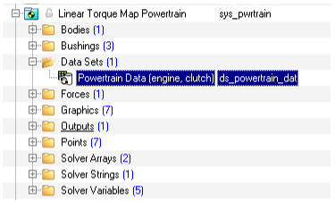
Powertrain
Linear torque map powertrain
Driver outputs required : Throttle
Compatible drivetrains : FWD, RWD, 4WD
Drive torque = Min. powertrain torque + (Normalized driver throttle output) *(Max powertrain torque - Min. powertrain torque)
Dataset can be used to enter the data required by the powertrain.
Data
|
Type
|
Comment
|
Throttle scaling
|
Real
|
Max driver throttle output –
Min driver throttle output
|
Max. powertrain torque
|
Real
|
Torque at drive joint at 100% throttle.
|
Min. powertrain torque
|
Real
|
Torque at drive joint at 0% throttle.
|
Transmission efficiency
|
Real
|
Output omega/Input omega of the drive train.
|
IC Engine Friction Clutch Powertrain (Manual transmission)
Powertrain that models IC Engine and friction clutch.
Driver Outputs Required : Throttle, Clutch, Gear
Compatible drivetrains : FWD, RWD
Drive torque is calculated based on the throttle map provided by the user in the pwr file. It also have features like rev limiter, anti-stall controller etc. Use IC Engine friction clutch manual for more details.
Brakes
Disk Brakes
This system models the disk brake and applies an opposing torque on the wheel joints proportional to the driver brake output. Read disk brakes documentation for more details.
Signal Generator
This system contains five signals which are used by driver for multiple use cases:
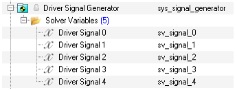
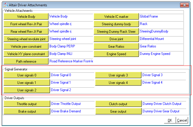
These signals are resolved as attachments under sub-heading signal generator in the driver attachment panel:
| 1. | Open Loop Signals or User defined signals. |
Example block in ADF
$------------------OPEN_LOOP_STEER
[OPEN_LOOP_MOTIONVIEW]
TAG = 'OPENLOOP'
TYPE = 'MOTIONVIEW'
SIGNAL_CHANNEL = 0
$---------------------------------------------
This block would link up the solver variable attached as OL Signal 0 as the throttle signal.
This functionality can be utilized to write user defined controllers by writing VARSUB or GSESUB.
| 2. | Open loop signals – expressions through ADF. |
User can directly override the solver variable through ADF file.
Example block in ADF
$------------------OPEN_LOOP_STEER
[OPEN_LOOP_EXPRESSION]
TAG = 'OPENLOOP'
TYPE = 'EXPRESSION'
SIGNAL_CHANNEL = 1
EXPRESSION = ‘SIN(TIME/2)’
$-----------------------------------------------------
This block would override the solver variable attached as OL Signal 1 to produce a sinusoid of amplitude 1 (angle model units) and frequency of 2 Hz.
| 3. | The above two methods are also used to generate control signals for feedback signals. |
$-------------------------------------FOLLOW_PATH
[LONG_PID_CONTROLLER]
TAG = 'PID'
TYPE = 'FOLLOW_VELOCITY'
DEMAND_SIGNAL = 'DEMAND_SPEED'
$------------------Read from demand signal block
I_ACTIVE_BAND = 2
KP = 100
KD = 20
KI = 10
INITIAL_ERROR = -5
$--------------------------------------DEMAND_SPEED
[DEMAND_SPEED]
TYPE = 'EXPRESSION'
SIGNAL_CHANNEL = 2
EXPRESSION = '10 + 5*SIN(TIME/3)'
$------------------------------------------------------------
These blocks are used to instantiate feedback traction controller which follows a control signal ’10 + 5*SIN (TIME/ 3)’.


