|
»Click here to display Table of Contents«
|

3D Shell - Edge Based |

|

|

|

|
|
3D Shell - Edge Based |
|
|
|

|
|
»Click here to display Table of Contents«
|
3D Shell - Edge Based |
|
|
|
|
|
3D Shell - Edge Based |
|
|
|
|
The 3D shell – edge based option allows you to define the *SURFACE card by specifying edge identifiers for 3D shell elements. The edges are displayed by special contactsurface elements. Face identifiers for solids with shell coating are defined by picking nodes on a specific edge and sweeping through a break angle. Therefore, the Nodes on edge option is always selected.
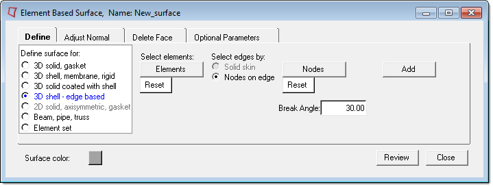
The 3D shell – edge based option has the following buttons:
Elements |
Opens the Element Selector panel and allows you to pick the underlying 3D shell elements from the graphic area. The selected elements are highlighted. The corresponding Reset button resets the selected elements. |
||
Nodes |
Opens the Node Selector panel and allows you to pick nodes from the graphic area. Two nodes from the same solid element must be picked to define a edge of that shell. The selected nodes are highlighted. The corresponding Reset button resets the selected nodes.
|
||
Add |
Finds all edges from the selected 3D shells that fall within a specified break angle of the edge(s) defined by nodes. These edges are then added to the current surface and special contactsurface elements are created for display.
|