The 3D solid or gasket elements option allows you to define the *SURFACE card by specifying face identifiers for individual solid and gasket elements. These faces are displayed by special face elements.
In order to create surface, you need to select the underlying solid or gasket elements first.
The Elements buttons opens the element selector panel and allows you to pick the underlying 3D solid or gasket elements from the graphic area. Selected elements are highlighted. The corresponding Reset resets the selected elements.
After that, you can define the face identifiers for the selected solids in two ways: (a) by creating a solid skin and manually picking the faces from the skin, (b) by picking nodes on a specific face and sweeping through a break angle. Select Solid skin option for (a) and Nodes on face option for (b) from the Select faces by: radio buttons.
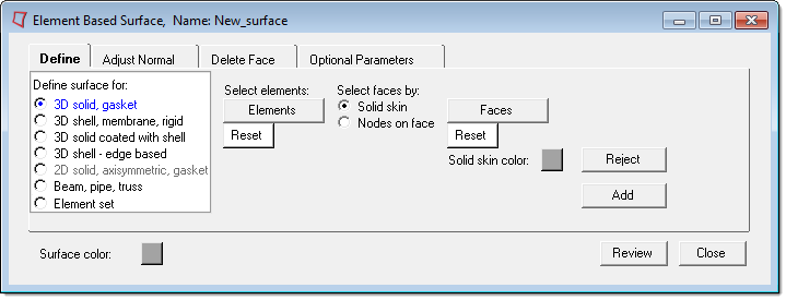
(a) Solid skin option has the following buttons:
Faces
|
Creates a temporary skin of the selected solids, opens the Element Selector panel, and allows you to pick face elements from this skin. The selected faces are highlighted. The corresponding Reset button resets the selected faces and deletes the skin.
| Note: | by face on the element selector panel can be used to find all faces within a feature angle of the selected face. The feature angle setting can be accessed by clicking the Preferences menu and selecting Geometry Options. |
The skin will initially have the same color as the current surface. You can change the skin color using Solid skin color: button.
|
Add
|
Adds the selected faces to the current surface and creates special face elements for display. It also checks for duplicate faces and displays a message if any are found.
| Note: | The Delete Face tab contains tools to find and delete duplicate faces in the current surface. |
|
Reject
|
Rejects the recently added faces.
|
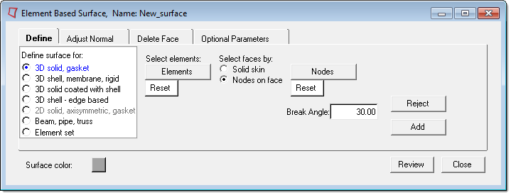
(b) Nodes on face option has the following buttons:
Nodes
|
Opens the node selector panel and allows you to pick nodes from the graphic area. Three nodes (or two corner nodes) from the same solid element must be picked to define a face of that solid. The selected nodes are highlighted. The corresponding Reset button resets the selected nodes.
| Note: | Several three-node or two-corner-node sets can be selected at the same time to define faces in different solids. |
|
Add
|
Finds all faces from the selected solids that fall within a specified break angle of the face(s) defined by nodes. These faces are then added to the current surface and create special face elements for display. It also checks for duplicate faces and displays a message if any are found.
| Note: | The Delete Face tab contains tools to find and delete duplicate faces in the current surface. |
|
Reject
|
Rejects the recently added faces.
|


