|
»Click here to display Table of Contents«
|

ACM Welds |

|

|

|

|
|
ACM Welds |
|
|
|

|
|
»Click here to display Table of Contents«
|
ACM Welds |
|
|
|
|
|
ACM Welds |
|
|
|
|
An ACM (Area Contact Method) weld is a special representation of a spot weld. The weld is defined using a solid (HEXA) element whose cross-sectional area is equivalent to the area of the weld nugget. The solid element is created at the exact weld location independent of the shell elements that represent the sheet metal parts. These solid elements are connected to the corresponding components using RBE3 elements. The size of the solid element is determined using the Diameter Table or using a specific value that you specify in the Spot panel. The spot weld diameter corresponding to the thickness ranges of the connecting flanges is obtained from the Diameter Table. The size of the hexa is calculated to match the cross-sectional area of the weld nugget.
The length of the weld element is calculated using one of the following methods:
|
This creates the hexa elements with a length equal to the average component thickness it is connecting. T1 and T2 are the component thicknesses. The first figure below shows the ACM weld created using this method. |
||
|
This creates the hexa elements between the component/element shell surface. The length of the hexa element will be equal to the actual distance between the two connecting components/elements. The second figure below shows the ACM weld created using this method. |
The figures below show ACM created using the two currently available methods.
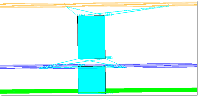
ACM creation using (T1+T2)/2.0 option
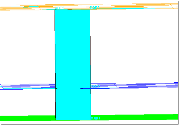
ACM creation using Project to Shells option
The weights of the RBE3 elements are calculated based on the projection of the dependent node on the shell element. The nodes of the shell element closest to the dependent node are assigned a greater weight relative to the node that is farther away.
ACM welds can be created and managed using connectors. Once a connector is created, they can be realized as ACM spotwelds as follows:
| 1. | Make sure that the connectors are created at each of the weld locations along with connecting parts information. |
| 2. | Make sure all the connecting parts have PSHELL cards with correct thicknesses. |
| 3. | Select the connectors to be realized as ACMs in the FE Realize panel of the Connectors module. |
| 4. | Choose custom element config and select type = Nastran 70 ACM((T1+T2)/2) or type = Nastran 71 ACM (Shell Gap) per your requirements. The appropriate property script is automatically loaded for the selected type. |
| 5. | Set the appropriate tolerance (proj tol=) value. |
| 6. | Make sure the attach to shell and snap to node options are turned off in fe options. |
| 7. | Select a DvsT file, which determines the size of the hexa based on the thicknesses of the components being connected. If no DvsT file is selected, hexas are created with weld nugget diameter =1.0 |
| 8. | Click realize. |