| 2. | Set the diameter/use diameter mapping toggle to use diameter mapping. |
| 3. | Click  . The Diameter Mapping dialog opens. . The Diameter Mapping dialog opens. |
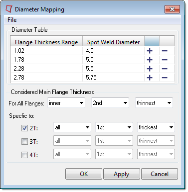
| 4. | Import or manually define flange thickness ranges and spot weld diameters in the Diameter Table. |
| • | To import predefined values, click File > Open from the menu bar. |
| • | To manually define values, click  to add a row to the table. Default flange thickness ranges and spot weld diameter values will be automatically interpolated. Edit these values accordingly. To remove a range from the table, click to add a row to the table. Default flange thickness ranges and spot weld diameter values will be automatically interpolated. Edit these values accordingly. To remove a range from the table, click  . . |
| 5. | For all flanges, define which flange thicknesses to consider when assigning diameter values. |
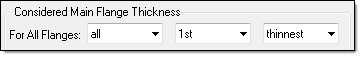
| • | From the first pull-down menu, select which flanges to consider: |
All
|
Consider all flanges.
|
Inner
|
Consider all of the inside flanges.
|
Outer
|
Consider the two outside flanges.
|
Middle
|
Consider the middle flanges. If there is an odd number of flanges, the very middle flange is considered. If there is an even amount of flanges, the two middle flanges are considered.
|
| • | From the second pull-down menu, select whether to consider the 1st, 2nd, 3rd, or 4th flange the meets the criteria in the third pull-down menu. |
| • | From the third pull-down menu, select whether to consider the thinnest, thickest, or average (average of all considered flanges, not only the thinnest and thickest) flange. |
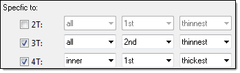
| 6. | Optional: If you are connecting 2T, 3T, or 4T thicknesses, you can specify specific flange thicknesses to consider when assigning diameter values to each layer. |
| 8. | Optional: To save the diameter mapping table, as well as the settings on how to determine the main flange thickness to a diameter mapping.txt file, click File > Save from the menu bar. |
When the connector is realized, only the flanges that meet the criteria defined in the Diameter Mapping dialog will be assigned a diameter value. The flange thickness ranges and spot weld diameter values defined in the Diameter Table will determine the diameter value that is automatically assigned to the spot weld diameter upon realization.
Example
Consider there are five flanges with the following thicknesses:
Flange 1 = 3.0
Flange 2 = 1.5
Flange 3 = 1.0
Flange 4 = 2.0
Flange 5 = 2.5
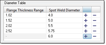
In the Diameter Table below, four sets of flange thickness ranges and spot weld diameter values have been defined. Below the table, the options have been set to only consider and assign a spot weld diameter to the inner flange with the 2nd thinnest thickness. If there is two layer thicknesses, all of the flanges will be considered, but only the 1st thickest flange will be assigned a spot weld diameter. In this example, there is only one layer.
When the connector is realized, flange 2 will be assigned a spot weld diameter of 4.0.
|


