Analytical Rigid Surface: Rigid Body Tab |

|

|

|

|
|
Analytical Rigid Surface: Rigid Body Tab |

|

|

|

|
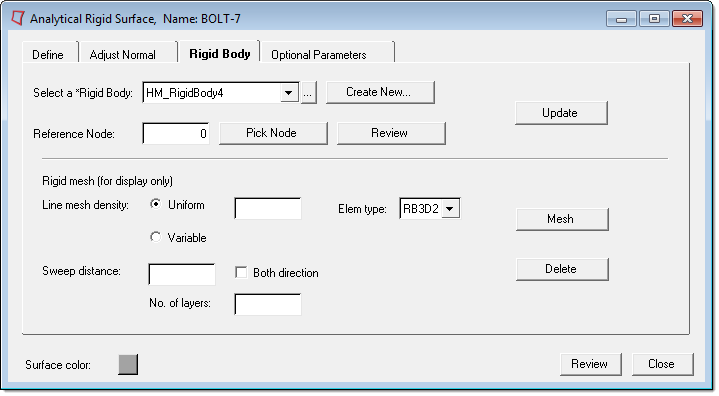
An analytical rigid surface must have a *RIGID BODY card with a reference node associated with it. When you create a new rigid surface in the Contact Manager, an empty *RIGID BODY component is created automatically. You can also associate the surface to an existing *RIGID BODY component or create a new one from this tab.
This tab also includes several options related to preparing the model for visualization in HyperView. HyperView currently does not support geometrical entities like analytical rigid surfaces. If you mesh analytical rigid surfaces with rigid elements that point to the same *RIGID BODY card, these elements would not participate in the analysis; they would move with the reference node as a rigid body. These rigid elements would act like a "display body" in Abaqus, and would be imported in HyperView.

Select the following options on the Rigid Body tab:
Select a *Rigid Body: |
Use the drop-down list or the Entity browser to select a rigid body. You can also create a new rigid body by clicking the Create New button. |
Reference Node: |
Type the node ID used as a reference to define the rigid body motion. Click Pick Node to pick a node from the model. Alternatively, type a node value in the box and click Review to view the location of the node in the model. (If you type a value that does not exist in the model, nothing is highlighted.) |
Line mesh density: |
Specify the density of the line mesh. Uniform uses the value you specify as the mesh density for each line segment. Variable brings you to the Line Mesh panel to create the mesh. Select either Uniform or Variable and click Mesh to create the line mesh. |
Sweep distance/ |
The sweep field differs depending on whether the surface is of type CYLINDER or REVOLUTION. If the surface is cylindrical, the field is Sweep distance. Type a value for the distance of the sweep of the mesh. Select the Both direction check box to extend the sweep in both directions for the specified distance. When the Both direction check box is selected, the number of layers refers to the depth of segments in the sweep (number of layers of elements). If the surface is a revolution, the field is Sweep angle. Type a value for the angle of the revolution. In the No. of layers field, type the value of how many segments the rim of the revolution should be divided into. |