|
»Click here to display Table of Contents«
|

CYLINDER Option |

|

|

|

|
|
CYLINDER Option |
|
|
|

|
|
»Click here to display Table of Contents«
|
CYLINDER Option |
|
|
|
|
|
CYLINDER Option |
|
|
|
|
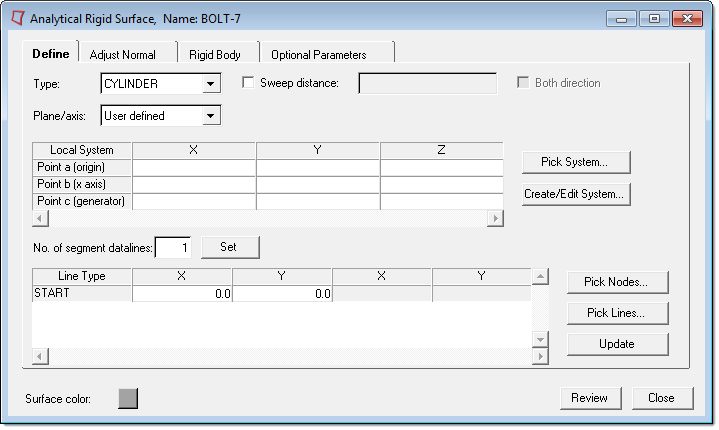
Analytical rigid surface of type CYLINDER
Select the following options on the Define tab for cylindrical rigid surfaces:
Plane definition |
|||||||||||||
Plane/axis: |
Choose User Defined if you want to create or select the system, or choose XY, YZ, or XZ to define it in the respective plane. If you choose to manually define the plane/axis, you must enter values for three points (the origin, x axis, and generator axis) that define the local plane on which the line segments will be defined. You can also use the following buttons to define the plane:
|
||||||||||||
Line definition |
|||||||||||||
No. of line segment datalines |
In this field you specify the number of datalines needed to define the line segments. The actual number of line segments is one less than this number. Start by typing the number of segment datalines to define the surface and click the Set button. The corresponding number of rows appears in the Line Type table below. In this table, specify the coordinates of the ends of each line segment. The first entry in the table is always the START node. This value specifies the beginning point of the first segment. The subsequent segments’ starting point is always the end point of the previous segment, or the START node if the segment is the first in the definition. For each line type, select a type from the Line Type column: LINE, CIRCL, or PARAB. Each selection activates the appropriate number of columns for the segment definition. The segments can be circles, parabolas, or lines. Enter data in the columns as described below:
You can also pick nodes or lines from existing geometry using the following buttons:
|
||||||||||||
Sweep Distance |
Abaqus does not need the sweep distance. The CYLINDER type surfaces are swept to infinity in Abaqus. However, in Engineering Solutions, you must define a sweeping distance to draw the three dimensional surface. Select the Sweep distance check box to specify a sweep distance and type a value in the adjacent box. Select the Both directions check box to sweep in opposite directions along the generator vector. |
||||||||||||
Click the Update button to update the database with your settings.