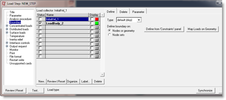
Define Boundary on: Nodes or Geometry |

|

|

|

|
|
Define Boundary on: Nodes or Geometry |

|

|

|

|
The Define Boundary on: Nodes or geometry option allows you to define various types of boundaries on individual nodes or geometry. Boundaries created on nodes have a special graphical display in Engineering Solutions. Loads created on geometric entities like surfaces, lines or points are automatically mapped to FEA mesh on export. You can also map them using the Map Loads on Geometry button.

The Define tab for Define Boundary on: Nodes or geometry has the following buttons:
Define from 'Constraints' panels |
Opens the Constraints panel to create/update boundary conditions. To create a boundary on nodes, go to the create subpanel, select the nodes button, pick the desired nodes from Engineering Solutions graphics, check the constrained degrees of freedoms, and click create. To create a boundary on geometry, go to the create subpanel, select surfs, points, or lines using the switch, pick the desired geometry from the graphics, check the constrained degrees of freedom, and click create. Notes:
|
||||||||
Map Loads on Geometry |
Opens the loads on geom panel to map loads on geometry to FEA mesh entities. Click Map loads to map all geometric loads in the current load collector to FEA entities. Note:
|
Load Step: Boundary: Define Tab