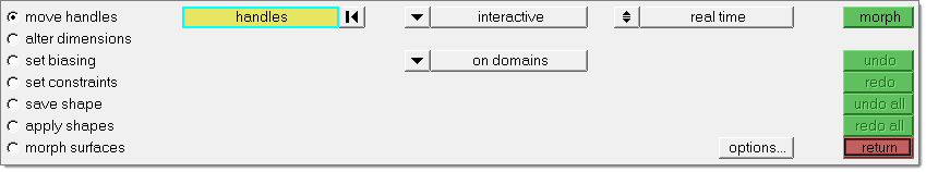
Use the Move Handles subpanel to move handles and morph a mesh.
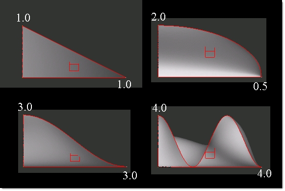
In the morph options panel, morphing subpanel, there is an option for setting the minimum step size for interactive morphing. If the distance or angle fields are set to values other than zero the morphing will be performed in discrete steps with the given step size rather than an arbitrary value based on the position of the mouse and relative to the size of the model. For example, setting the distance to 1.0 means that all interactive translation will be performed in increments of 1.0, such as 1.0, 2.0, 11.0, and so on. For distance, the value is given in model units. For angle, the value is given in degrees.
If the morphing is too slow, change from real time to on release (morphing will occur when you release the mouse button).
If you select more than one handle before selecting morph, those handles will follow the handle that you are dragging.
If you have enabled an auto quality check, it will highlight or color code the failed elements as you are morphing interactively. Click the mouse after morphing to return to normal graphics. If you have enabled auto smoothing, smoothing will occur either in real time or on release depending on the selected setting in the Morph Options panel. If you have enabled auto remeshing and the percentage of morphed elements which fail the quality criteria is larger than the specified fail %, you will be given the option of remeshing the morphed elements. Right-click to remesh and left-click to continue without remeshing. After remeshing you have the option of rejecting the remeshing. Right-click to reject the remeshed elements and left-click to accept them.
| Note: | This is your only chance to reject the remeshing. Once you have accepted the remeshed elements, clicking undo button will not reject the remeshing. |
|
If you have enabled fea results, an FEA solution will be performed in real time or on release depending on the selected setting in the morph options panel.
If you have any reflective symmetries (1-plane, 2-plane, 3-plane, and cyclical) in the model, the movements of any handles attached to the domains assigned to those symmetries will automatically be reflected to all linked handles.
Panel Inputs
Input
|
Description
|
(movement type switch)
|
This switch contains options to determine the method or type of movement for the selected handles.
| • | interactive: Drag handles across the screen using the mouse. |
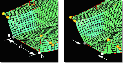
Interactive morphing (set to screen) using the on plane option:
| • | translate: Apply a perturbation to selected handles. |
If you select more than one handle before clicking morph, those handles will have the same perturbation applied to them, except when using the along normal option.
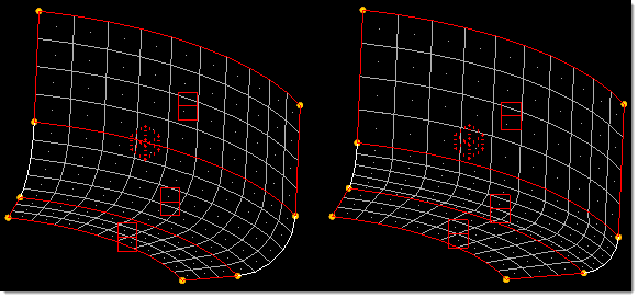
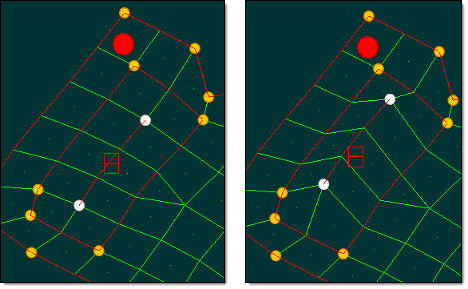
The figure below illustrates morphing using translate. A bead is created by moving the handles at the ends of the edge domain (highlighted) in the positive z direction.
| • | rotate: Apply a rotation to selected handles. |
Some areas of your model (most notably curved edges) may end up distorted or out of plane after handles are rotated. To alleviate this problem, you should undo the rotation and add handles in the areas of the model that are becoming distorted or are not rotating properly. To completely eliminate the distortion of edge domains during rotation, you can add a handle at every node of the edge domain using the handles on edge command in the edit edges subpanel of the Domains panel.
If you wish to do a simple rigid body rotation and this panel is unable to accomplish it, try using the Freehand panel’s record subpanel. That tool allows you to morph using any panel. In this case, you would click start (in the record subpanel), go to the Rotate panel, rotate your mesh, return to the Freehand panel, record subpanel, and click finish. This will convert your rotation into a morph and can be undone, redone, and saved as part of a shape.
| • | scale: Scale selected handles relative to a node. |
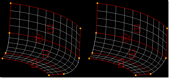
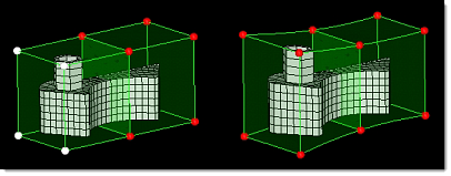
The figure below illustrates morphing using scale. A morph volume face is enlarged by 20% relative to the center of the face.
| • | move to XYZ: Select a handle and move it to the specified XYZ coordinates. |
| • | move to node: Select a handle and move it to a position where a node is currently located. |
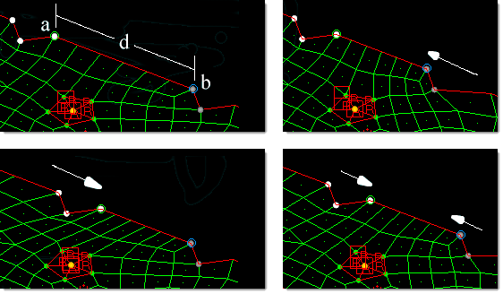
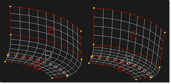
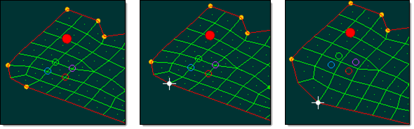
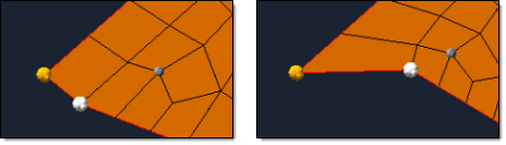
This example illustrates morphing using move to node. A handle is selected (white) followed by a node (gray). The handle moves to the position of the node and the mesh morphs accordingly.
Note: The target node also moves with the mesh, to a new location.
You can use this feature to move handles to lines or surfaces since Engineering Solutions allows you to create nodes on the fly. Instead of selecting a node, hold down the mouse button when selecting a line or surface, then click the line or surface where you want the node. The node is created and the handle moves to the new position.
| • | move to point: Select a handle and move it to a position where a point is currently located. |
| • | project to line: Project selected handles to a line. |
| • | project to plane: Project selected handles to a plane. |
| • | project to surf: Project selected handles to a surface. |
| • | project to mesh: Project selected handles to a mesh. |
|
(on/along what switch)
|
These options determine where the movement is allowed to take place, including in what directions. The option you choose affects which additional inputs display, as noted in the descriptions below.
The default is manipulator, which creates an interactive “triad” which can be translated and rotated by clicking parts of it and dragging the mouse. The translations and rotations of the triad are then applied to the selected handles, domains, or morph volumes, thus morphing the mesh in real time.
Starting in release 12.0-SA110, you can also choose to use a manipulator.
If you choose manipulator, you may switch the entity selector to allow you to select handles, domains, morph volumes, morph volume edges, or morph volume faces. When you select one or more entities, a triad manipulator will appear on the screen at the center of those entities. You may then click and drag one of the three arrows of the manipulator to translate the entities, click and drag one of the three arcs of the manipulator to rotate the entities about the center of the manipulator, or click and drag one of the three right angles of the manipulator to move the entities in a plane. You may also select or unselect entities while the manipulator is active, changing which entities are affected by the manipulator. If no entities are selected, the manipulator will disappear.
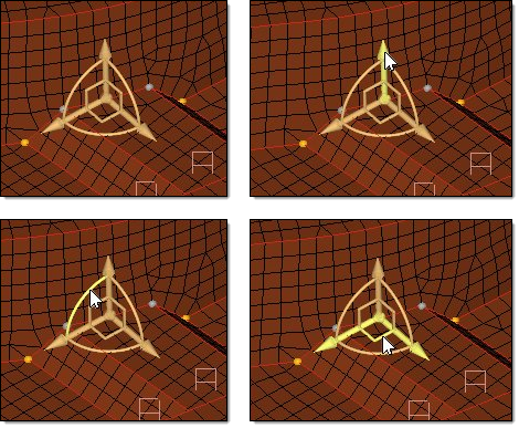
The images below show a triad manipulator and where to click on it to translate it along a vector, rotate it about an axis, or translate it in a plane.
The position of the manipulator will be set at the center of the selected entities unless an origin node has been specified in which case the manipulator will remain at the specified node until the manipulator is moved. Selecting new entities will update the position of the manipulator unless an origin node is specified. Selecting or updating an origin node will reposition the manipulator at the new node without morphing the model. An origin node is helpful when you wish to rotate entities about a given point.
The orientation of the manipulator will be aligned with the global axes by default. You may update the orientation of the manipulator to be aligned with a local coordinate system or to a specified vector or plane by using the toggles and selectors below the manipulator selector. Reorienting the manipulator in this way will not morph the model.
When rotating the manipulator, the options constant rotation and linear rotation are available as well as the true rotation option. If constant is selected, all handles will be rotated about the axis equally relative to the manipulator. If linear is selected, all handles will be given a rotation proportional to the distance that they are from the origin of the manipulator as measured along the axis of rotation. The handle farthest from the origin of the manipulator is rotated the full amount and the others are rotated according to the ratio of their distance to the origin compared to the distance of the handle farthest from the origin. Leave true rotation unchecked if you only wish to rotate the handles, with the mesh morphed linearly according to their new locations. When checked, true rotation rotates both the nodes and the handles with the amount of rotation for the nodes being proportional to the amount of influence of the handles over those nodes. (See the notes in Move handles using rotate, below, for images of how true rotation affects morphing).
You may create more than one manipulator at a time by switching the toggle between single manipulator and multiple. When switched to multiple, clicking the new manip button will allow you to create a new manipulator by selecting another entity. The different manipulators may have different parameters and can be moved independently of one another. Moving a manipulator, clicking a manipulator, or simply moving the mouse over one of the manipulators will cause the panel to be updated to parameters for that manipulator, allowing you to change the parameters or the entities associated with them if you desire.
The manipulators can be set to be active or inactive by switching the toggle to either manip:active or manip:inactive. When active the manipulators will morph the model when moved. When inactive the manipulators will only change their own position and orientation when moved.
For manipulators, “on release” features such as the large domain solver will not be invoked until the mouse is moved out of the graphics area, enabling you to make multiple perturbations of the manipulator without delay. The exception to this rule is if auto quality checking or interactive fea are currently active, in which case the “on release” features will be invoked when you release the mouse.
|
| • | If you choose on domains, HyperMesh creates a surface out of the elements on the domains to which the selected handle is attached. This option can only be used for handles that are attached to 2-D domains. |
| • | If you choose off domains, the morphing is similar to on domains, but it allows you to move the handle off the neighboring domains with its position being calculated roughly perpendicular to the plane of those domains. |
| • | If you choose along xyz or along vector, you must also specify a direction along which the interactively selected handle will move. |
| Note: | For cylindrical and spherical systems, checking the box labeled use system for nodes will move influenced nodes relative to the local system instead of following the handles. |
| • | If you choose along line, on plane, or on surface, you must also specify the line, plane or surface along which the interactively selected handle will move. |
| Note: | For the on plane option you do not need to select a base point for the plane if you have the use handle for base checkbox checked. Also for the on plane option you may change the toggle to infer from handles which will automatically determine a plane that runs roughly through the selected handles. For best results select three or more handles which lie roughly in a plane. |
| • | If you choose along normal, you must also select elements whose normals you wish to use. The selected handles must lie on the selected elements. |
| Note: | All handles selected will move along normals calculated for the selected elements which they are touching and may move in different directions than other handles. |
| • | If you choose along mvol edges, you must also select the morph volume edges along which you wish the handles to move. You may select multiple groups of edges provided that each group connects end to end and intersects with at least one of the selected handles. HyperMorph will extend the ends of the edges approximately one morph volume length beyond the end to allow you to move handles past the end of their morph volumes. |
| • | If you choose scale, you must also select the scaling factors in the x, y, and z directions as well as the system used to define those directions. Use the toggle to specify the origin for scaling either by selecting a node or by using the average position of all of the selected handles. Clicking the uniform button allows you to update the x, y, and z scaling factors simultaneously. |
|
along mvol edges
|
When morphing along mvol edges, use this selector to pick the desired edges.
|
along vector: plane and vector selector
|
This switch option is available for translate, project to line, project to surf, and project to mesh morphs.
Use the standard selector to define or pick the vector along which to morph.
|
angle =
|
When rotating handles, this is the number of degrees to rotate by.
|
avg for origin / origin =
|
When morphing by scale, this switch lets you choose between using the average of the selected handles' coordinates for the origin, or picking a specific node as the origin.
If using the avg for origin option you must select more than one handle to morph.
|
constant/linear
|
This field displays when rotating handles.
| • | If constant is selected, all handles will be rotated about the axis by the given angle. |
| • | If linear is selected, all handles will be given a rotation proportional to the distance that they are from the base node as measured along the axis of rotation. The handle farthest from the base node is rotated the full amount and the others are rotated according to the ratio of their distance to the base node compared to the distance of the handle farthest from the base node. |
|
handles
|
Use this selector to pick the handles you wish to move. Moving handles morphs the mesh of their dependent nodes.
|
line
|
When morphing along line, use this selector to pick the desired line.
|
node
|
When morphing by move to node, use this selector to pick the node that you wish to move the selected handle(s) to.
|
normal to geom
|
This switch option is available for project to line, project to surf, and project to mesh morphs. It sets the projection direction normal to the target geometry (line list, surfs, or elems).
|
normal to elems: all 2D elems / elems
|
This switch option is available for project to line, project to surf, and project to mesh morphs. It sets the projection direction normal to elements touching the handles, or normal to specific elements that you pick via the elems selector.
|
on plane: plane and vector selector / infer from handles
|
Use this switch to choose between the two methods of defining the plane.
| • | Use the standard selector to define the plane. You do not need to specify the base node if the use handle for base checkbox is active. |
| • | infer from handles automatically determines a plane that runs roughly through the selected handles. For best results select three or more handles which lie roughly in a plane. |
|
options
|
This button opens the morph options panel.
|
point
|
When morphing by move to point, use this selector to pick the geometric point that you wish to move the selected handle(s) to.
|
project to plane: x-axis / y-axis / z-axis / vector / N1, N2, N3
|
When projecting to a plane, this switch presents several options for determining the position and orientation of the plane. Each option also requires a base node (B node collector).
| • | X, Y, and Z axes refer to the default global coordinate system. |
| • | Vector requires you to select an existing vector entity. |
| • | N1, N2, N3 allows you to define the plane's normal vector by using two nodes (N1 and N2) or by using all three nodes via the right-hand rule. The base node is used to position the plane. |
|
project to plane: normal to geom / normal to elems / N1, N2, N3 / x-axis / y-axis / z-axis
|
When projecting to a plane, this switch presents several options for determining the direction to project.
| • | normal to geom. Projects the handles along the plane normal. |
| • | normal to elems. Projects the handles along the normals of the elements to which the handles are attached. |
| • | N1, N2, N3. Enables you to define a vector. Use N1 and N2 to define a vector with two points and use N1, N2, and N3 to define a vector using the right hand rule. |
| • | X, Y, and Z axes. Refers to the default global coordinate system. |
|
real time / on release
|
This option is only available for interactive morphing. When real time is active, morphing occurs while you move the handles; when set to on release, the morphing only occurs once you release the mouse button.
|
rotation axis
|
When rotating handles, use the plane and vector selector to define a vector. This vector (at the base node) is the axis of rotation, and its positive direction is determined via the right-hand rule.
|
surf
|
when morphing on surface, use this selector to pick the desired surface.
|
system =
|
This collector/numeric field displays when the on/along what switch is set to along xyz or scale. Use it to (optionally) specify a local coordinate system for the translation or scaling dimensions--otherwise the default global system is used.
|
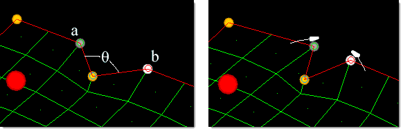
true rotation
|
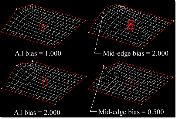
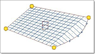
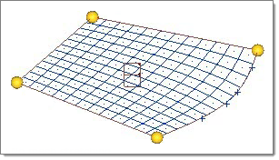
Leave true rotation unchecked if you only wish to rotate the handles, with the mesh morphed linearly according to their new locations (left image, following). When checked, true rotation rotates both the nodes and the handles, with the amount of rotation for the nodes being proportional to the amount of influence of the handles over those nodes. (right image, following).
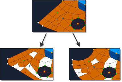
This sequence shows the difference between normal rotation (left) and true rotation (right). Note how true rotation causes straight edges to curve. This is because each node is being rotated about the selected axis rather than moved linearly.
|
x scale, y scale, z scale
|
These three numeric boxes display when the on/along what switch is set to scale. They allow you to specify the magnitude/distance in each axis for the scaling, in model units.
|
x value, y value, z value
|
These three numeric boxes display when the on/along what switch is set to move to xyz. They allow you to specify the distance in each axis for the translation, in model units
|
uniform
|
When morphing by scale, click this button to set all of the X, Y, and Z values to the same number. A pop-up allows you to enter the desired number, and displays the average of the three existing values by default.
|
use all elems / elems
|
When morphing along normal, use this switch to set the direction as the average of all involved elements' normals, or to pick specific elems.
|
use system for nodes
|
This checkbox displays when the on/along what switch is set to translate or scale. This option moves influenced nodes relative to the local system instead of following the handles.
|
|