|
»Click here to display Table of Contents«
|

Map to Geom panel |

|

|

|

|
|
Map to Geom panel |
|
|

|

|
|
»Click here to display Table of Contents«
|
Map to Geom panel |
|
|
|
|
|
Map to Geom panel |
|
|
|
|
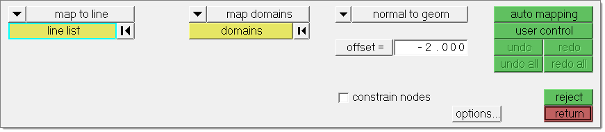
The Map to Geom panel allows you to map nodes, domains, morph volume edges, or morph volume faces in your model to a line, node list, plane, surfaces, elements, or an equation using edge domains and handles to guide the process. It also allows you to map a mesh to section lines, apply the difference between two lines or two surfaces to a mesh, offset a mesh in the normal direction, and map (or create) a mesh to a surface interpolated from a set of nodes or lines.
The Map to geom panel does not include any subpanels, but its layout changes dynamically depending on the options chosen, beginning with the type of geometry you wish to map to.
You can complete inputs in any order, but since the panel layout can alter depending on the inputs chosen, it is best to work from left to right to avoid negating any settings you've already made if an "earlier" input setting changes the options for inputs you have already selected.
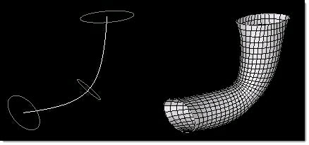
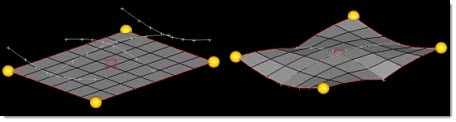
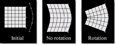
The following is an example of Map to Geom. The marked nodes and line are selected in the picture on the left and the fit to line option chosen. The picture on the right shows the results of clicking the automap button. Engineering Solutions distributes the selected nodes along the specified line, and the rest of the mesh stretches to accommodate the mapping.
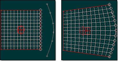
Here, the left-side handles remain fixed and all of the elements stretch.
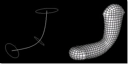
Below is an example of map to geom with following handles. The same line is selected, but instead of a node list, the edge domain closest to the line is selected. Mapping by domains enables the user control button, which accesses a new panel. In this example the two handles on the left are chosen as followers before clicking the map button. The follower handles are given perturbations similar to those of the mapped nodes and follow along behind them.
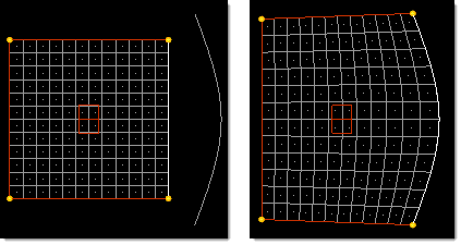
Here, the left-side handles move with the mesh based on their distance from the line.
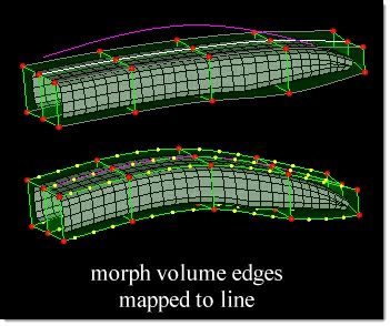
In the following example the highlighted morph volume edges are mapped to the line while the dimmed edges are selected as follower edges. The highlighted edges are mapped directly to the line while the follower edges are given a similar morphing.
|
The User Control panel can also be used to place handles and edge domains before the previously selected mapping operation takes place. This capability is useful when mapping a mesh to a surface. After selecting the mesh and surface you can go to the User Control panel and fit each edge of the mesh to the lines around the surface. Then when you map, the mesh will be fit to the surface.
Nodes and domains can be mapped directly to several different types of entity, or mapped using one of several indirect methods. See the options for (mapping type switch) in the Inputs table below.
There are no subpanels on the Map to Geom panel. All inputs and command buttons are located on the main panel.
Input |
Description |
|||||||||||||||||||||||
(at location switch) |
When using map to equation, this switch allows you to choose the start point for the function:
|
|||||||||||||||||||||||
(covariance switch) |
This switch displays when the map type is interpolate surf. Covariance is the local variations of the interpolation around the drift (see drift switch below). The values h, h^2log(h), and h^3 give progressively more precise interpolations, while exp(-1/x) will give an approximate interpolation. |
|||||||||||||||||||||||
(drift switch) |
This switch displays when the map type is interpolate surf. Drift is the global trend of the interpolation. The values of no drift, constant, linear, quadratic, and cubic give progressively more precise interpolations while trigonometric uses a unique interpolation approach. |
|||||||||||||||||||||||
(interpolation method switch) |
For interpolate surf mappings, this switch replaces the (map direction switch). It allows you to pick the method by which a surface will be interpolated.
Click to see some examples.
|
|||||||||||||||||||||||
(map direction switch) |
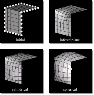
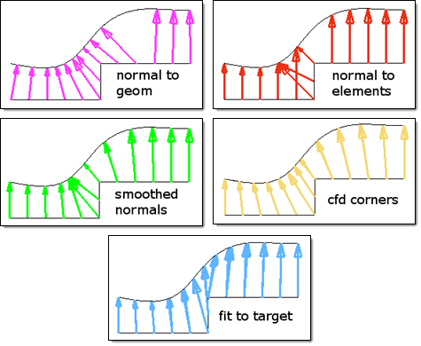
This third switch displays for all direct mapping types (to lines, nodes, planes, surfs, elems, or equations). It determines the direction of mapping:
For other mapping types, this switch is replaced by the (map by switch) (for section or line difference), the along vector / about axis toggle (for surface difference), or the interpolation method switch (for interpolate surf.) Each of those alternative inputs is described separately in this table.
Examples:
In the images above, note how the mesh (viewed in profile) is projected to a curved surface using each available option. The fit to target option is ideal for mapping an edge or 2D domain to a line or surface. It will stretch or shrink the mesh to fit the target geometry, distributing the interior nodes evenly, while the other options simply project the nodes on to the target (or to the closest edge of the target) in the chosen direction. The normal to geom option works well for most mapping cases but will occasionally fold, bind, or stretch the mesh. For cases where your mesh contains sharp corners and you wish to use the mesh to determine the projection direction, the cfd corners option will produce the smoothest projections. However, it can be time consuming, and for meshes without such sharp corners the smoothed normals option will work quickly while giving good results. For a gently flowing mesh, the normal to elements option can also give a smooth final mesh. |
|||||||||||||||||||||||
(map by switch) |
When the mapping type is section or line difference, this switch replaces the (map direction switch). It determines what type of entity or feature guides the mapping process. The first four methods of linear mapping differ in how the nodes are projected towards the section lines, which determines how each line influences the nearby mesh. With linear mapping the entities are mapped directly:
|
|||||||||||||||||||||||
(mapping type switch) |
The first switch on the panel allows you to select the type of mapping operation that you wish to perform, and influences which additional input fields display. Options include:
|
|||||||||||||||||||||||
(map what switch) |
When mapping by any direct method (to lines, nodes, planes, surfs, elems, or equations), the second switch on the panel defines what you wish to map to the target entities. Options include:
When mapping with indirect methods (to sections, line difference, surface difference, normal offset) this switch is replaced by the map what toggle described below. |
|||||||||||||||||||||||
(map what toggle) |
When mapping with indirect methods (to sections, line difference, surface difference, normal offset) this switch allows you to pick between map domains and map elements, or in the case of line difference or surface difference, choose between map domains and map nodes. |
|||||||||||||||||||||||
along vector / about axis |
For surface difference mappings, this toggle replaces the (map direction switch). It allows you to specify an axis to map around or a vector to map along. Either option presents a standard plane and vector selector, though the resulting vector is used differently. |
|||||||||||||||||||||||
blend % |
When the map type is interpolate surf, also input the blend %, which is how much of the difference between the selected entities and the interpolated surface will be applied to the mesh. At 100%, the entities will be placed on the interpolated surface. At 50% the entities will be placed halfway between the interpolated surface and their initial positions. |
|||||||||||||||||||||||
constrain nodes |
Check constrain nodes if you wish to create a new morph constraint for the mapped nodes. The selected nodes will be constrained to the chosen entities during subsequent morphs. To remove a constraint, use the release nodes subpanel in the Morph Constraints panel, or simply delete the constraint. |
|||||||||||||||||||||||
domains |
When mapping domains, use this selector to pick the domains you wish to move. |
|||||||||||||||||||||||
elems |
When mapping elements, use this selector to pick the elements you wish to move. |
|||||||||||||||||||||||
extend edges |
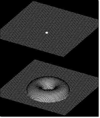
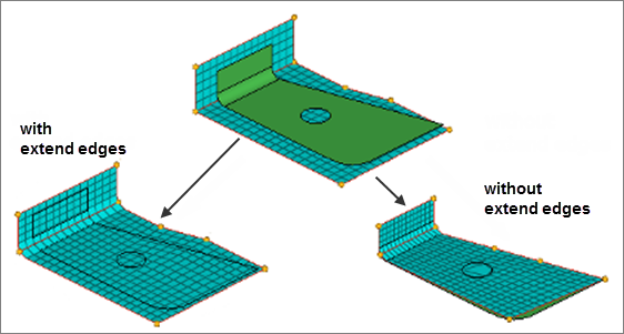
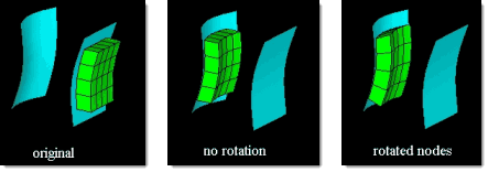
When using map to surfaces or map to elements, the extend edges checkbox will appear, enabling you to extend the edges of the surfaces or mesh in a direction perpendicular to the normal at the closest point on the surfaces or mesh. If this checkbox is selected, the mapped nodes will be projected on to an extended representation of the surfaces or mesh, allowing you to project nodes beyond the edge of the surfaces or mesh as well as within any holes. If this checkbox is not selected, the mapped nodes will be projected on to the interior or edges of the surfaces or mesh.
In the example above, three surfaces float above an angled mesh divided into two 2D domains. Both domains are selected to be mapped to the surfaces in the normal to geom direction. With extend edges selected, the nodes of the domains are moved either to the surfaces or to virtual surfaces which are extended perpendicular to the normal direction at the edge of the surface. Notice how the nodes end up placed inside the hole in the center of the largest surface. Without extend edges selected, the nodes of the domains are moved to the nearest point on the surfaces. Notice that whenever you map nodes and elements which are part of domains, the handles are mapped first, expanding or compressing the surrounding mesh, which helps to reduce mesh distortion. In this case it succeeded in reducing mesh distortion around the edges of the surfaces, but not around the hole. |
|||||||||||||||||||||||
F(xyz)
|
This switch displays when using map to equation, and presents a number of preset functions and function groups that you can choose from based on geometry. When you pick an option, such as hyperboloid 2, the relevant math function(s) automatically fill in the first available alphanumeric boxes located below the switch. You can modify these equations, or type in your own. The function F(xyz) may contain x, y, and z variables with the rest being numbers or expressions. If using the selector to obtain a function for a standard shape, you should replace constants a, b, c, r, and R with numbers. The surface defined when the function is set to zero will be used as the target surface for the mapping. Use the prev and next buttons to create additional pages for your function if there is not enough space in the first page. |
|||||||||||||||||||||||
fixed nodes / no fixed nodes |
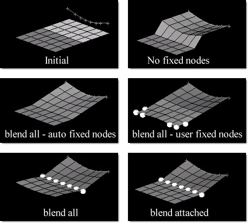
This toggle displays when the map type is map to sections or line difference. If you select fixed nodes then you may also select the type of blending that you want between the mapped sections and the fixed nodes.
If you do not select any nodes as fixed nodes, but the toggle is still set to fixed nodes, HyperMorph automatically selects the nodes nearest the selected domains or elements that do not lie on those domains or elements.
|
|||||||||||||||||||||||
follower nodes |
This selector displays when the map type is map to sections. Follower nodes are not mapped to the sections, but follow the basic morphing of nodes that are mapped. |
|||||||||||||||||||||||
from line: |
This selector displays when the map type is line difference and works in conjunction with to line (described elsewhere in this table.) Use it to select the starting line for your mapping. |
|||||||||||||||||||||||
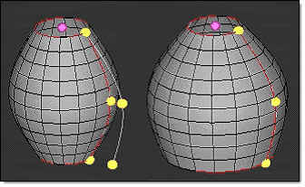
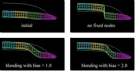
fx bias = |
This numeric field displays when the map type is line difference or surf difference. Higher values result in nodes between the mapped nodes and fixed nodes staying closer to fixed nodes. In the example below, the cyan and yellow components are mapped to the line, first with no fixed nodes, then with both the mv bias and fx bias set to 1.0 and the magenta component fixed, then with both the mv bias and fx bias set to 2.0 and the magenta component fixed.
|
|||||||||||||||||||||||
handle placement: use current / handles/edge |
When the (map what switch) is set to map mvol edges or map mvol faces, use this switch to choose between keeping the current number and arrangement of handles on the morph volume edges, or typing in a different number (up to 5 handles) for each morphed edge. |
|||||||||||||||||||||||
line list |
When using map to line or map to sections, use this selector to pick the line(s) that you wish to map to. |
|||||||||||||||||||||||
lines / line list (toggle) |
When using map to section, this toggle allows you to select the lines or line list to which you wish to map. Use the separate line list selector (above) to designate the destination lines. |
|||||||||||||||||||||||
map domains / map nodes |
This toggle displays when the map type is line difference. This setting determines what actually gets mapped to the section lines. In either case, you must select the domains or nodes that you wish to map using the line difference. |
|||||||||||||||||||||||
map elements / map domains |
This toggle displays when the map type is map to sections and the lines / line list toggle is set to lines. This setting determines what actually gets mapped to the section lines. In either case, you must select the domains or elems that you wish to map to the section lines. |
|||||||||||||||||||||||
mapped edges |
When the (map what switch) is set to map mvol edges, use this collector to specify the morph volume edges that you wish to serve as the mapping target. |
|||||||||||||||||||||||
mapped faces |
When the (map what switch) is set to map mvol faces, use this collector to specify the morph volume faces that you wish to serve as the mapping target. |
|||||||||||||||||||||||
mv bias = |
This numeric field displays when the map type is line difference or surf difference. Higher values result in nodes between the mapped nodes and fixed nodes following the mapped nodes more closely. |
|||||||||||||||||||||||
node list |
When the (map what switch) is set to map node list, use this collector to specify the nodes that you wish to serve as the mapping target. |
|||||||||||||||||||||||
no follower edges / follower edges |
When the (map what switch) is set to map mvol edges, use this toggle to choose between using follower edges (which must be picked with the supplied collector) or not using any. Follower edges mimic the shape change of the mapped edges. You can also change the number of handles on follower edges via the handle placement toggle, if desired. |
|||||||||||||||||||||||
no follower faces / follower faces |
When the (map what switch) is set to map mvol faces, use this toggle to choose between using follower faces (which must be picked with the supplied collector) or not using any. Follower faces mimic the shape change of the mapped mvol faces. The procedure will map the edges of the selected faces to the selected plane, surface, mesh, or equation which will generally map the face as well. However, since morph volume faces are defined purely by their edges, the middles of the mapped faces may not perfectly match the features to which they were mapped. You can also change the number of handles on follower faces via the handle placement toggle, if desired. |
|||||||||||||||||||||||
normal calculation: use selected elems / use all elems |
When mapping along a normal offset, use this toggle to use either all elements when calculating the normal direction or to use only the elements being mapped. |
|||||||||||||||||||||||
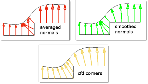
normal calculation: averaged normals / smoothed normals / cfd corners |
When mapping along a normal offset, use this selector to define how the normal direction is determined.
|
|||||||||||||||||||||||
nugget: off / nugget = |
This switch displays when the map type is interpolate surf. Nugget controls how close the interpolated surface will fit relative to the control points. If the nugget is off or set to zero, the interpolated surface will pass through all the control points. If the nugget is on and non-zero, the interpolated surface will not necessarily pass through all the control points. The larger the nugget value is, the farther away the interpolated surface is allowed to be from the control points. |
|||||||||||||||||||||||
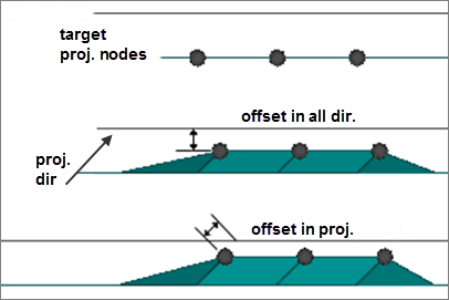
offset = |
When mapping to a line, a node list, a plane, surfaces, elements, or an equation, you have the option of setting how far the nodes will be offset from the target. Although the mapped nodes will be moved in the specified projection direction, the offset will be the absolute distance, in model units, the mapped entities will end up from the target regardless of the direction in which they were moved. A positive value for the offset will place the nodes short of the target, a negative value for the offset will place the nodes beyond the target, and an offset of zero will place the nodes on the target. When mapping along a normal offset, the offset distance is how far the selected elements are moved from their present positions in their normal directions. A positive value will offset the elements in the direction of the element normal and a negative value will offset the elements opposite the direction of the element normal. |
|||||||||||||||||||||||
offset in all dir. / offset along proj. |
When mapping entities to a node list, line, plane, surface, or mesh while using a non-zero offset, you may select offset in all dir, which will measure the offset from each node to the closest point on the target, or offset along proj, which will measure the offset from each node to the target along the direction of projection.
In the picture above, three nodes are being offset from a plane along a vector which is at a forty-five degree angle to the plane normal. When offset in all dir is selected, the offset is measured from each node to the closest point on the target plane, in this case along the plane normal. When offset in proj is selected, the offset is measured from each node to the plane along the projection vector. Note that when using the offset in proj option, the nodes can end up closer to the nearest point on the target than the value of the offset. |
|||||||||||||||||||||||
rotate nodes: |
This checkbox displays when the map type is line difference or surf difference. When mapping nodes from a straight line to a curve, check rotate nodes if you wish the curvature of the new line to affect the whole mesh.
Line difference with rotate nodes.
surface difference with rotate nodes. |
|||||||||||||||||||||||
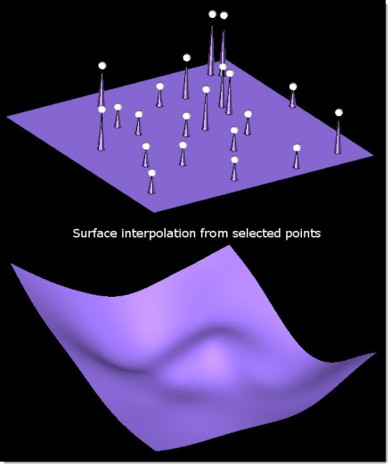
target nodes: / target lines: |
When the map type is interpolate surf, this toggle allows you to select between target nodes and target lines and pick the nodes or lines through which the surface will be interpolated. If you selected target lines, type in the number of target nodes per line in the n/line field. The larger the number of nodes per line, the more accurate the mapping will be. As a general rule, select no more than 3000 target nodes, as the surface interpolation algorithm will use a large amount of memory and CPU time. |
|||||||||||||||||||||||
to line: |
This selector displays when the map type is line difference and works in conjunction with from line (described elsewhere in this table.) Use it to select the starting line for your mapping. |
The following action buttons appear:
Button |
Action |
auto mapping |
Performs the mapping operation based on all available input. |
map |
Performs the mapping operation based on all available input. |
redo |
Redoes the last "undone" operation. |
redo all |
Redoes all "undone" operations. |
reject |
Undoes the creation of an entity, such as a constraint or shape. |
return |
Exists the panel. |
user control |
Launches the user control subpanel to allow manual completion of the mapping operation. |
undo |
Undoes the most recent morphing action (movement of nodes, but not creation of entities such as constraints). |
undo all |
Undoes all recent morphing actions (movement of nodes, but not creation of entities such as constraints). |
Changing a Curvature Using Map to Geometry - HM-3530