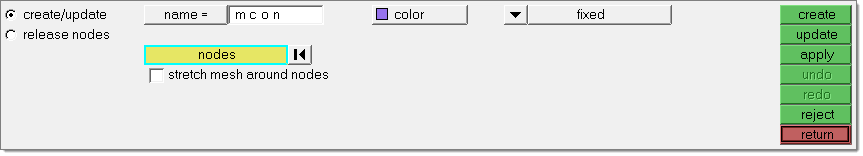
Use the Create/Update subpanel to create a new constraint, or to select and modify an existing one.
A constraint is set to be active when it is created, meaning that the constraint will be applied automatically whenever the model is morphed. To change a constraint's active status, go to the Morph Options panel or click the options… button and go to the morphing subpanel. Click the morphconstraints collector to modify which constraints are active and which are not.
| Note: | Constraints will only be applied if the use constraints checkbox is checked. |
|
When a constraint to a line, plane, surface, elements, or an equation is applied, the nodes will be moved to that feature and the node movement will be stored as a morph that can be undone and redone. However, undoing a morph that occurred as part of constraining nodes will not remove the constraint. To remove a constraint after it has been applied, you will need to do one of the following: use the reject button, use the release feature on the release nodes subpanel, or delete the constraint (via the delete panel).
Nodes may be part of multiple constraints. In these cases, HyperMorph will perform a series of iterations to try to satisfy all of the constraints. For instance, a node constrained to two intersecting surfaces will be moved to a point along the interface between those surfaces. If all of the constraints cannot be met for a given node, HyperMorph will return a warning.
When morphing, constraints are applied after the nodes or handles are morphed. In some cases this may change the amount of morphing applied to the handles or nodes. For instance, when rotating handles which are constrained to move along a line, the handles will first be rotated by the given amount and then moved to line, possibly altering the angle applied to the handles. This is true for all morphing operations except when the distance or angle is changed in the Morph panel, alter dimensions subpanel, which will iterate until both the desired distance or angle is met and the constraints have been satisfied.
For tangency constraints, you are allowed to create tangency "chains" by joining as many 2-D or edge domains as desired and even make loops, although master-slave loops and other insolvable configurations are not allowed. Also, while the 2-D domain tangency option is fairly robust, its performance may not be satisfactory when long, curving chains of domains are made tangent to each other. In those cases, the interpolate surf feature in the Map to Geom panel can be used to smooth the mesh.
When a model constraint (length, angle, radius, arc angle, area, volume, or mass) is applied, the shapes associated with the constraint will be applied to the model in order to enforce the constraint. For example, if you have a model that must weigh no more than a certain amount you can create a mass constraint that uses a shape which varies the total width of the model. From then on, after every morph, HyperMorph checks the current weight of the model and, if the model is too heavy, it applies the shape, reducing the width of the model, so that the weight does not exceed the value set in the mass constraint.
Constraints are not retroactive when applied. Morphs in the undo list as well as saved shapes will not be updated to match any constraints that you create afterward. You can update an existing shape to be constrained by removing all morphs, applying the shape with the constraint active, and saving the shape to the same name.
The following inputs are found on the Create/Update subpanel. To make finding a specific input easier, inputs are listed in alphabetical order instead of attempting to follow the subpanel layout. This is necessitated by the fact that many inputs are used by multiple constraint types, and thus their descriptions often refer to each other.
| Note: | Switches with no overall label are alphabetized according to their default option. |
|
Panel Inputs
Input
|
Description
|
along vector:
|
This option only displays for along vector constraints. Use this standard plane and vector selector to define the vector along which the nodes may travel.
|
angle
|
Appearing when the constraint type is angle, this numeric box allows you to specify an angle value to constrain nodes to. This works in conjunction with the equal to /upper bound / lower bound switch and calculate button.
Clicking twice on the angle label/button opens the calculator pop-up.
|
at origin / at node / at system
|
This switch only displays for on equation constraints. Choose the starting point of the path defined by the equation--at node and at system both reveal new entity selectors so that you can pick the desired node or local coordinate system, while at origin simply uses the origin point of the default global system.
|
arc angle
|
Appearing when the constraint type is arc angle, this numeric box allows you to specify an angle value to constrain nodes to. This works in conjunction with the equal to /upper bound / lower bound switch, calculate button, and find center / center axis / center line / center node switch.
Clicking twice on the arc angle label/button opens the calculator pop-up.
|
area
|
Appearing when the constraint type is area, this numeric box allows you to specify a total area to constrain nodes to. This works in conjunction with the equal to /upper bound / lower bound switch, calculate button, and elems selector.
Clicking twice on the area label/button opens the calculator pop-up.
|
(constraint type switch)
|
Use this switch to pick the constraint type. See the table above for details on each type.
Different constraints change the options that display on the panel.
|
color
|
Click this box to open a standard color palette and select a color for the constraint entity.
|
calculate
|
This button displays when the constraint type is length, angle, radius, arc angle, area, volume, or mass. Clicking it calculates the current value of the constraint. For example, after selecting nodes for the node list, click this button to automatically place the total length of the node list into the length field above it.
|
connected edge domains
|
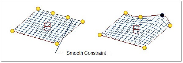
This option only appears for smooth constraints. Use the selector to pick the edge domains connected to the constraint.
|
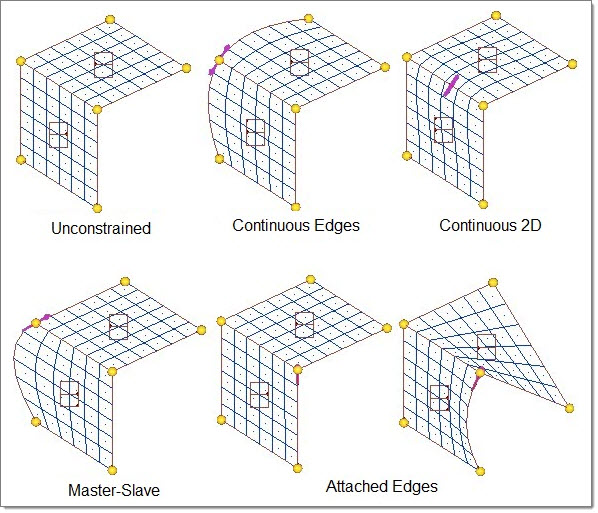
continuous / master-slave / fixed end / attached
|
These options only appear for tangency constraints.
| • | For continuous, master-slave, or attached tangencies, select two domains to be constrained—one for each domain selector. |
| Note: | Continuous type is the only tangency type available for 2-D domains. |
| • | For the fixed end tangency, select an edge domain to be constrained, the node at the end which is to be constrained, and a vector to orient the end of the edge domain. |
|
create generic
|
This button displays when the constraint type is length, angle, radius, arc angle, area, volume, or mass. Clicking it generates a shape which, when applied, changes the target constraint value. For example, once you have specified a node list, you can click this button to quickly create a basic morph shape that changes the length of the node list.
|
domain
|
Two of these selectors display when the constraint type is set to tangency. Use them to pick the domains between which the tangency constraint exists.
|
elems
|
This selector only displays for on elements, area, volume, or mass constraints. Use the selector to pick the mesh elements to which the nodes are constrained.
For area, volume, or mass constraints, the area/volume/mass is calculated from the selected elements (before morphing) and that total area/volume/mass is maintained after morphing, though the shape of the element cluster can change:
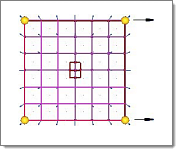
area constraint on elements
|

|
shape changes, but total area (L x W) is preserved
|
|
equal to / upper bound / lower bound
|
This switch displays when the constraint type is length, angle, radius, arc angle, area, volume, or mass.
The choice made here directly affects how the value in the length field is used:
| • | equal to ensures that the node list's overall length does not change. |
| • | upper bound allows the node list to contract, but not to expand beyond the specified length. |
| • | lower bound allows the node list to expand, but not to contract to less than the specified length. |
|
exclude beyond
|
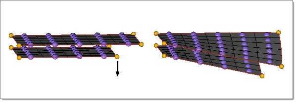
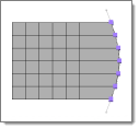
Opens a dialog from which you can exclude any selected nodes which are either beyond a certain distance or beyond a given number of rows of elements away from the selected elements. It is available only for the on elements type morph constraint
In the dialog there are two collectors which match the contents of the nodes and elements in the panel. You can modify the selected nodes and elements by double-clicking these collectors.
The dialog also contains an entry field which you can use to type in the number of model units or number of element rows. After the entry field there is a selector which you can use switch between model units and element rows.
If model units is selected, any nodes beyond the given number of model units will be excluded from the selected nodes. If element rows is selected, any nodes beyond the given number of element rows away from the selected elements will be excluded from the selected nodes. Note that for element rows, the rows of elements must be attached to the selected elements and all nodes not a part of the rows of elements will be excluded.
When exclude is clicked, any nodes beyond the given criteria are removed from the selected nodes. If no nodes have been selected, all the nodes in the model which are not attached to the selected nodes are placed on the mark and those beyond the given criteria are then excluded from the mark.
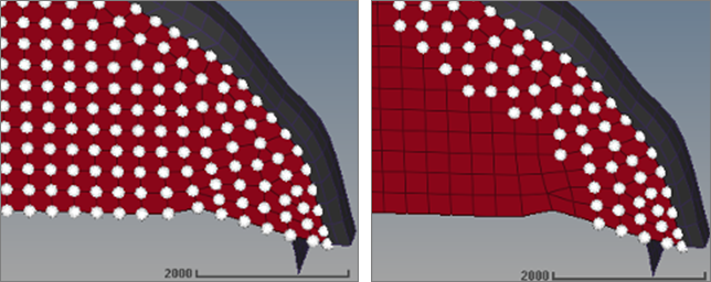
The images above shows how the exclude beyond functionality is used. In the image on the left, all of the nodes for the crimson mesh and the elements shown in gray are selected for an on elements type morph constraint. Using the exclude beyond dialog, model units is selected as the distance option and a distance of 1000.0 is used to exclude all of the nodes which are more than a thousand model units away from the selected elements. In the image on the right, the exclude has been clicked and the nodes left on the mark are those at or within one thousand model units of the selected elements.
|
find center / center axis / center line / center node
|
This switch works in conjunction with the edge domain selector to help determine the correct value for the radius or arc angle numeric boxes.
| • | find center infers the center from the plane of the edge domain. |
| • | center axis requires you to use a plane and vector selector to specify a plane and base node. The axis is the plane's normal at the base node. |
| • | center line requires you to specify the desired line. |
| • | center node requires you to specify the desired node. |
|
F(xyz)
|
This button and corresponding text fields only display for on equation constraints. Click the switch to open a list of predefined equations; picking one automatically fills in the text fields with an equation. You can edit these equations if necessary. Make sure to replace constants a, b, c, r, and R with numbers. For some more complex shapes defined by more than one equation (such as a torus) the corresponding equations fill into each of the two text fields.
You can also type in your own function. The function may contain x, y, and z variables with the rest being numbers or expressions. The surface defined when the function is set to zero will be used as the boundary for the constraint.
| Note: | You can add more equations by means of the prev and next buttons. |
|
fix dofs:
|
Use the three checkboxes to constrain the degrees of freedom of the nodes for a given coordinate system for an along dofs constraint. Use x translation (r) to fix the x or r coordinate of each node with respect to the coordinate system. Use y translation (theta) to fix the y or theta coordinate of each node with respect to the coordinate system. Use z translation (phi) to fix the z or phi coordinate of each node with respect to the coordinate system.
|
fixed at: node
|
This selector only displays when the constraint type is set to tangency and the tangency type is fixed end.
This node is the fixed point for the end which is to be constrained.
|
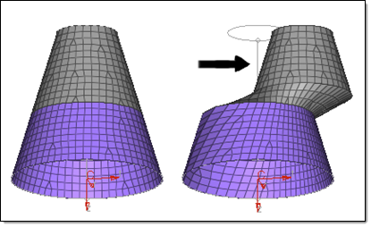
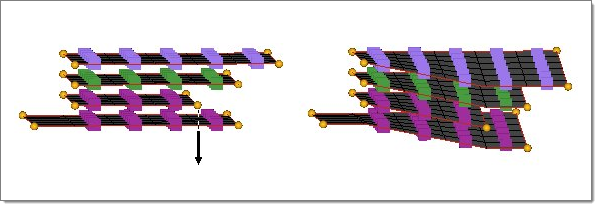
fully fixed / translate only / force normal / allow sliding
|
This selector allows you to control how the inner layers of a fixed layers style constraint on elements will move when the outer layer is morphed.
| • | fully fixed. Translates and rotates the inner nodes to match changes in the constraint elements, preserving the initial distance and orientation. |
| • | translate only. Translates the inner nodes to match changes in the constraint elements, preserving the initial distance. |
| • | force normal. Identical to the fully fixed option, except that it will force the inner nodes to lie normal to the constraint elements when the constraint is created. |
| • | allow sliding. Similar to the translate only option, except that it will allow the inner nodes to move perpendicular to the normal direction as long as the initial distance in the normal direction is preserved. |
|
global system / syst
|
Use the toggle to switch between the global system and a local system of your choosing for an along dofs constraint. The degrees of freedom of the system selected will be used for all the nodes of the constraint.
|
length
|
Appearing when the constraint type is length, this numeric box allows you to specify a total length value to constrain nodes to. This works in conjunction with the equal to /upper bound / lower bound switch, calculate button, and node list selector.
Clicking twice on the length label/button opens the calculator pop-up.
|
line
|
This option only applies for along line constraints. Use the selector to pick the line along which nodes are allowed to move.
|
mass
|
Appearing when the constraint type is mass, this numeric box allows you to specify a total mass value to constrain nodes to. This works in conjunction with the equal to /upper bound / lower bound switch, calculate button, and elems selector.
This value is calculated based on the area/volume of the selected elems, and density data supplied by a property card. The total mass remains fixed after morphing, even if the shape of the element cluster changes.
Clicking twice on the mass label/button opens the calculator pop-up.
|
measured along: node list / N1N2 / x-axis / y-axis / z-axis
|
This switch determines what vector or path the length is measured along.
| • | node list uses the node list already specified under the length switch. |
| • | N1N2 displays two buttons to allow you to pick two nodes in the mesh. The length is measured along the line between them. |
| • | x-axis, y-axis, and z-axis measure the length along the chosen axis of the default global coordinate system. |
|
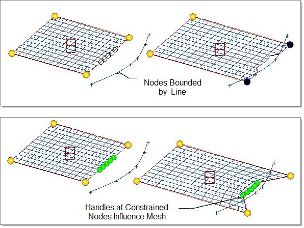
moves along / bounded / set distance / fixed layers
|
This switch only displays for the constraints along vector, along line, on plane, on surface, on elements, and on equation. Each type of constraint involves different additional inputs, which display when the combination of constrain type and moves along / bounded / set distance / fixed layers is selected (each of these additional fields are described later in this table).
| • | moves along. Enables inputs to define an entity, vector, or equation along which the nodes are permitted to move during a morph operation. |
| • | bounded. Enables inputs to define a location past which the nodes will not travel, and to specify a minimum distance = to maintain from this boundary (in which case they will approach, but not reach, the boundary). |
| • | set distance. Enables the distance = text box as above. However, the distance= text box can also be toggled to maintain, which keeps the constrained nodes at their current distance from the bounding plane during morphing operations. |
| • | fixed layers. Enables multiple layers of nodes to be positioned at the initial distance they were from the target elements. It is very similar to the set distance option with maintain selected, but is faster and has some more powerful features. This option was developed specifically for CFD meshes where thin boundary layers of matching nodes are commonly used. |
|
measured normal to:
|
This switch appears for angle constraints, and determines what the angle is measured relative to. Options include:
| • | abv plane: The angle is determined normal to the plane defined by the node a, vertex, and node b selected above. |
| • | N1N2: This option displays a new set of N1 and N2 node selectors. The angle is defined normal to the line that they define. |
| • | x-axis, y axis, or z-axis: The angle is measured normal to the global axis that you choose. |
|
name =
|
To create a new constraint, type in a new name.
To update an existing constraint, either type in its name, or click the button twice and select the desired constraint from the menu that displays.
|
node a / vertex / node b
|
Use this set of buttons to define the angle for angle constraints. Once you define these nodes, you can use the calculate button to automatically fill in the angle numeric box.
|
nodes
|
Either pick the nodes to be constrained individually in the graphics area, or use the extended entity selection menu to pick groups of nodes by certain criteria.
|
node list
|
This selector only displays when the constraint type is length. Select nodes to define the boundaries of the length constraint, and to enable the use of the create generic and calculate buttons, as well as the use of the node list option for measured along.
|
on plane:
|
This plane and vector selector only displays for on plane constraints. Use the selector to define the plane to which the nodes are constrained.
|
project along:
|
This toggle only applies for along line, on plane, on surface, on elements, or on equation constraints. Nodes that you select which don't already lie on the constraint entity will be projected to it in this direction.
In addition, during morphing the nodes constrained to such entities may move off of them, but will then be projected in this direction back onto the constraint entity when the morph action finishes. (If you want the nodes to remain exactly fixed, without sliding along the entity, use a fixed constraint for them instead.)
| • | normal projects the nodes along the constraint entities' normal direction. |
| • | The standard plane and vector selector lets you determine the direction by picking an axis/vector or using the normal of a plane. |
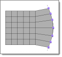
Projection to line normal
|
Project using a vector
|
|
radius
|
Appearing when the constraint type is radius, this numeric box allows you to specify a radius value to constrain nodes to. This works in conjunction with the equal to /upper bound / lower bound switch and calculate button. The radius is measured using an edge domain and one of the following methods for finding the center of curvature: an axis, a line, a node, or inferred from the plane of the edge domain.
Clicking twice on the radius label/button opens the calculator pop-up.
|
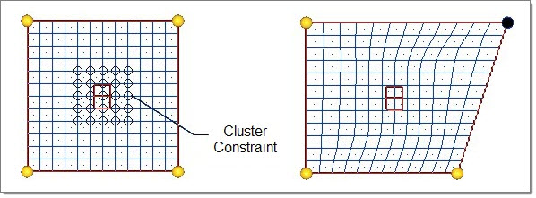
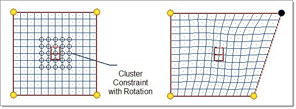
(rotation switch)
|
When the constraint type is constraint, use this switch to choose between no rotation, tilt only, spin only, and full rotation.
| Note: | The spin (in plane)and tilt (out of plane) options only apply for cluster constraints whose nodes all lie in a plane. If the nodes do not lie in a plane, any rotation option is considered full rotation. |
Cluster constraint
|
|

With no rotation
|
With spin or full rotation enabled
|
|
shapes
|
This selector displays when the constraint type is length, angle, radius, arc angle, area, volume, or mass.
Use this selector to pick the pre-existing shapes. You can also create generic shapes from the node list.
|
smooth nodes / smooth dep. handles
|
This option only appears for smooth constraints. Choose whether to apply the spline-based motion of smooth edge constraints to the nodes directly, or to dependent handles between the morphed handles.
|
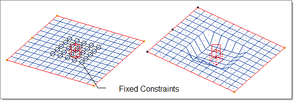
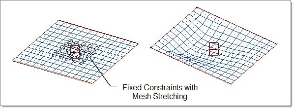
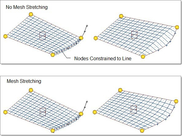
stretch mesh around nodes
|
When active, the mesh near the constrained nodes will be stretched proportionally to their distance from the nodes, in order to create a smoother resulting mesh.
No mesh stretching
Mesh stretching activated
|
surf
|
This selector only displays for on surf constraints. Use the selector to pick the surface to which the nodes are constrained.
|
volume
|
Appearing when the constraint type is volume, this numeric box allows you to specify a total volume value to constrain nodes to. This works in conjunction with the equal to / upper bound / lower bound switch, calculate button, and elems selector.
Clicking twice on the volume label/button opens the calculator pop-up.
|
|