Use the Create subpanel to create a single volume, or a matrix of volumes, enclosing nodes or elements.
The following methods of creation are supported:
Method
|
Description
|
create morphvol
|
This is the default method, which involves selecting the elements or nodes that you wish the new volume to contain.
|
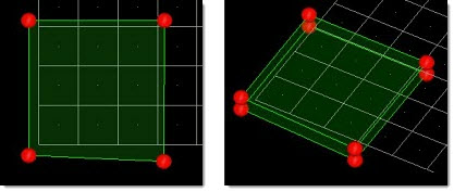
pick and enclose
|
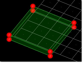
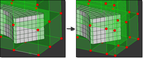
This method relies on selecting nodes to indicate where you wish your new volume’s corner handles to be. It works in two ways:
| • | You can select a node for each of the eight corners of the new morph volume. |
| • | If your model contains at least one morph volume, you can create a new volume adjacent to an existing one by selecting nodes on the face of the existing volume (and optionally designating the elements or nodes that you wish the new volume to contain). HyperMesh creates a new volume, joined to the first, which either contains those nodes/elements, or which extends outward a distance equal to the average length of the edges on the selected face. |
|
|
|
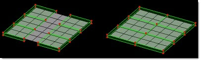
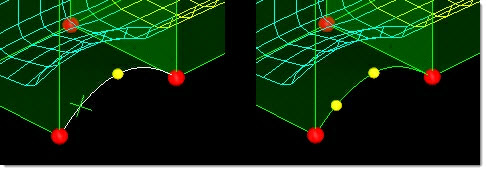
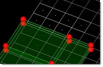
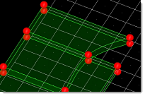
Note the gray-highlighted elements
|
|
The new mvol comforms to the shape of the selection.
|
|
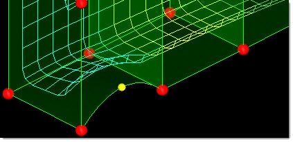
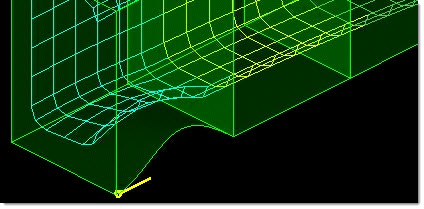
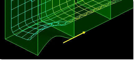
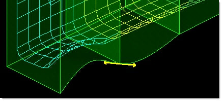
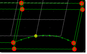
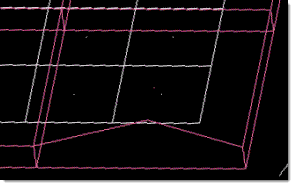
pick on screen
|
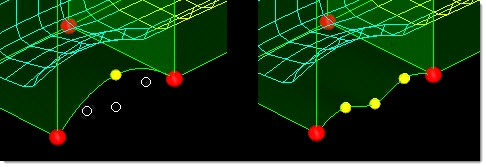
This method allows you to simply draw the two-dimensional boundaries of the new morph volume directly on-screen. The new morph volume will be given sufficient depth to enclose all the nodes selected within the window.
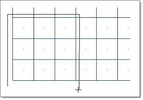
Here, 3 of 4 lines have been laid down. When the 4th is laid, HyperMesh creates a new morph volume matching its shape and thick enough to enclose the relevant elements.
|
reflect morphvols
|
This method allows you to select one or more reflective symmetries and create new morph volumes by reflecting existing ones.
|
create matrix
|
This method creates a uniform matrix of connected morph volumes. As morph volumes are three-dimensional, you can create a single-layer matrix of morph volumes (for example, nine volumes in a 3x3x1 matrix) or a multi-layer matrix (such as a 3x3x3 cube). Additionally, if you select a cylindrical coordinate system for the matrix, the matrix will be oriented around the central axis of the system.
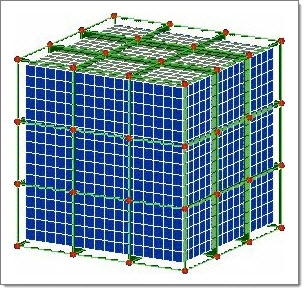
This rectangular matrix has X,Y,Z density of 3,3,3
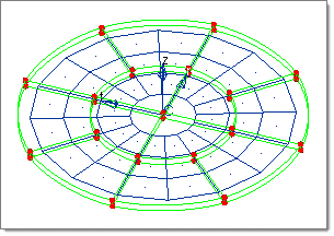
This cylindrical matrix has R, theta, Z density of 2,8,1
|
drag morphvols
|
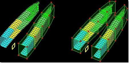
This method allows you to select existing morph volumes and drag their faces through a mesh, along a line or nodelist, along a vector, or about an axis.
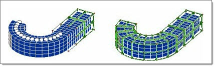
Volumes dragged along a node list
Volumes spun about an axis
|
drag elements
|
This method allows you to select shell elements and drag them through a mesh, along a line or nodelist, along a vector, or about an axis.
|
drag matrix (rect)
|
This method allows you to create morph volumes in a rectangular configuration through a mesh, along a line or nodelist, along a vector, or about an axis.
|
drag matrix (cyl)
|
This method allows you to create morph volumes in a cylindrical configuration through a mesh, along a line or nodelist, along a vector, or about an axis.
|
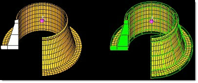
drag lines (rect)
|
This method allows you to create morph volumes in a rectangular configuration with the outer profile matched to selected lines and drag them through a mesh, along a line or nodelist, along a vector, or about an axis.
Profile lines dragged along a line to create morph volumes.
|
drag nodes (rect)
|
This method allows you to create morph volumes in a rectangular configuration with the outer profile matched to a list of nodes and drag them through a mesh, along a line or nodelist, along a vector, or about an axis.
|
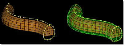
drag lines (cyl)
|
This method allows you to create morph volumes in a cylindrical configuration with the outer profile matched to selected lines and drag them through a mesh, along a line or nodelist, along a vector, or about an axis.
|
drag nodes (cyl)
|
This method allows you to create morph volumes in a cylindrical configuration with the outer profile matched to a list of nodes and drag them through a mesh, along a line or nodelist, along a vector, or about an axis.
|
Panel Inputs
Input
|
Description
|
auto-tangent
|
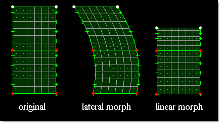
If tangency is selected, a continuous tangency condition will be applied across adjacent edges for the new morph volumes. Tangency ensures smooth morphing between morph volumes.
| Note: | Tangency conditions can extend across multiple morph volumes, meaning that handle movements at one end of the morph volume matrix can potentially affect every morph volume. |
|
buffer %
|
This determines the amount of empty space between the selected nodes or elements and the faces of the created morph volumes, based on the average size of the morph volume to be created. For instance, if a mesh measured 30x30x30 and a 10% buffer percentage was selected, the morph volume would be created measuring 36x36x36, which would give it a 10% (3 unit) buffer zone between each side and the enclosed mesh.
|
(create method switch)
|
The first switch on the panel presents all of the creation methods described above. The option that you pick influences which of the remaining inputs display on the rest of the panel.
|
(drag direction switch)
|
This switch displays when using any of the "drag" creation methods.
| • | along mesh will drag the morph volume faces or elements along a line that runs roughly through the centroid of the selected nodes or elements. |
| • | along line drags the morph volume faces or elements along a line. |
| • | along nodelist drags the morph volume faces or elements along a line created from a list of nodes. |
| • | along vector will drag the morph volume faces or elements in the specified direction. Use the toggle to select whether to drag for a specified distance or far enough to enclose the selected elements or nodes. |
| • | about axis will spin the morph volume faces or elements about the specified axis. Use the toggle to select whether to drag through a specified angle or far enough to enclose the selected elements or nodes. |
|
elems (drag elements)
|
Use this collector to select the elements you wish to drag.
|
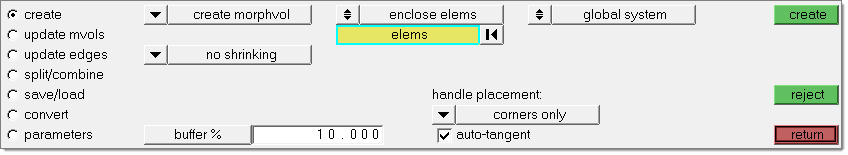
enclose elems / enclose nodes
|
Use this toggle to change the entity selector below it; then, use the selector to pick the entities that you wish the morph volume to enclose.
|
(fit method switch)
|
A second switch allows you to determine what, if anything, the morph volume can do after creation to better fit the elements that it encloses:
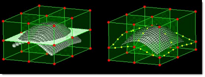
| • | shrink depth: appearing only when the creation method is pick on screen, this fit method will shrink the morph volume only in the direction of the screen vector (the corners will remain at the positions you selected). |
| • | no shrinking: no shrinking is applied to the morph volumes upon creation, but you may shrink or fit them later using the shrink mvols or fit faces features in the update mvols subpanel, or you may adjust them manually by making the mvols inactive and then morphing their handles. |
| • | shrink mvols: the morph volumes which are created will be shrunk around the mesh to match the specified buffer % value. The implicit mode algorithm will be used to perform the shrinking. |
| • | slide faces: slide faces will slide the faces normal to their orientation, maintaining the orientation angles and shapes of the faces. |
| • | tilt faces: tilt faces will change the orientation angles of the faces but maintain the shapes. |
| • | fit faces: fit faces will change the shapes of the faces if there are mid-handles on the face edges, otherwise it will tilt the faces. |
|
global system / local system
|
global system creates the new morph volume with coordinates relative to the default global coordinate system; local system adds a syst selector to allow you to pick the desired local coordinate system to associate the new volume with.
|
handle placement:
|
This switch determines where the morph volume's handles are located:
If you choose corners and edges, you must also specify the number of handles to create on each edge. You can specify 1 to 5 edge handles, which will be evenly spaced along the edge between the corner handles.
|
morphvolumes
|
This entity collector displays when the creation method is reflect mvols. Use it to pick the existing morph volumes that you wish to reflect in order to create new volumes.
|
node list
|
This entity collector displays when the creation method is pick and enclose or drag nodes. Use it to select the nodes that you wish to enclose or drag.
|
on drag
|
This numeric box displays when the creation method is any of the "drag" options.
This is the number of morph volumes that will be created along the drag direction. Thus, if you had selected six morph volumes and set on drag to 5, a total of 30 (6 x 5) new morph volumes will be created.
|
on face x
|
This numeric box displays when the creation method is drag matrix (rect), drag lines (rect), or drag nodes (rect).
On face x and on face y are the number of morph volumes which will be created for a rectangular matrix in the local x and y directions. The local x direction is determined as being either the global x axis as projected on to the plane normal to the drag direction, or if the drag direction is perpendicular to the global x axis then the projection of the global y axis is used. The local y direction is perpendicular to the local x direction and the drag direction.
|
on face y
|
This numeric box displays when the creation method is drag matrix (rect), drag lines (rect), or drag nodes (rect).
On face x and on face y are the number of morph volumes which will be created for a rectangular matrix in the local x and y directions. The local x direction is determined as being either the global x axis as projected on to the plane normal to the drag direction, or if the drag direction is perpendicular to the global x axis then the projection of the global y axis is used. The local y direction is perpendicular to the local x direction and the drag direction.
|
register all inner nodes
|
This option displays when the create method is pick and enclose or reflect mvols. It associates all nodes enclosed by the morph volume with that volume.
The process of registering nodes allows you to do two things: One is to control which nodes are morphed by morph volumes and which are not (such as when you are matching one mesh to another), and the other is to make one morph volume dependent on another by registering its handle nodes to a morph volume that encloses it.
After morphing morph volumes while they are inactive, unregistered nodes may end up inside the morph volumes. These will not be automatically registered when the morph volume status is switched to active. You will need to register these new nodes manually.
|
r density
|
This numeric box displays when the creation method is drag matrix (cyl), drag lines (cyl), or drag nodes (cyl).
r density is the number of morph volumes which will be created in the radial direction.
|
symmetries
|
This entity collector displays when the creation method is reflect mvols. Use it to select the reflective symmetry around which you wish to reflect the specified morphvolumes.
|
t density
|
This numeric box displays when the creation method is drag matrix (cyl), drag lines (cyl), or drag nodes (cyl).
t density is the number of morph volumes which will be created in the outer layer about the drag axis.
|
X density / Y density / Z density
|
When the creation method is create matrix, These values are the number of morph volumes that will be created along each axis.
For example: when creating a single-layer, 3 x 3 matrix of volumes around a 2-D mesh, you might specify 3 for the X and Y densities and 1 for the Z density.
For a cylindrical matrix, the x density refers to the number of morph volume layers in the radial direction and the y density refers to the number of morph volumes in the outermost ring.
|
|