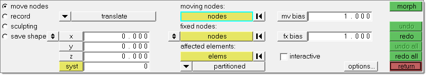
Use the Move Nodes panel to directly move specific nodes to new locations while morphing the surrounding mesh.
Using the Move Nodes subpanel, you can translate and rotate nodes, move nodes normal to a mesh, move nodes to a vector, node list, line, plane, surface, mesh, or equation, and apply a shape. For each morphing option, you can choose whether or not the morphing should be interactive. You can also control how those node movements apply to the surrounding mesh.
| Note: | In the Morph options panel, Morphing subpanel, there is an option for setting the minimum step size for interactive morphing. If the distance or angle fields are set to values other than zero the morphing will be performed in discrete steps with the given step size rather than an arbitrary value based on the position of the mouse and relative to the size of the model. For example, setting the distance to 1.0 means that interactive translation will be performed in increments of 1.0, such as 1.0, 2.0, 11.0, and so on. For distance, the value is given in model units. For angle, the value is given in degrees. The minimum step size applies when using the manipulator or using the translate, rotate, or move normal options. |
|
Panel Inputs
Input
|
Description
|
(edge bounding method switch)
|
This switch displays when you morph nodes with selected fixed nodes and affected elements.
| • | Partitioned: Partitions all of the affected elements according to the values set in the Domain panel, partitioning subpanel before applying morphing. |
| • | Inferred Edges: Local domains are created for the affected elements for the purpose of applying the morphing. Edge domains will be created along the boundaries of the affected elements which will regulate morphing. |
| • | Free Edges: A general domain is created for the affected elements for the purpose of applying the morphing. The movement of nodes along the boundaries of the affected elements is unregulated. |
| • | Use Domain Edges: If you have already created domains, those domains will be used to determine the way the morphing is applied to the model. |
| • | Morph All Nodes: Using a proximity based algorithm, potentially every node in the model will be morphed relative to the distances between the nearest moving node and the nearest fixed node. |
| • | Krig All Nodes: Using the kriging algorithm, potentially every node in the model will be morphed except for the fixed nodes. The options used for kriging can be modified in the Morph Options panel, domain solvers subpanel which can be accessed by clicking the options… button. |
| Note: | A practical upper limit on the number of moving nodes you can have is 3000. Computers with above average memory and CPU available may be able to support larger number of moving nodes comfortably. |
| • | Morph Within Envelope: Using a proximity based algorithm, potentially every node in the model will be morphed relative to the distances between the nearest moving node and to either the edge of the envelope or the nearest fixed node (if selected). The envelope can either be defined as a discrete distance using the fix at distance option, or as a multiple of the magnitude of the perturbation applied to the nearest moving node using the fix at multiple option. If the fix nodes option is selected, this method will act identically to Morph All Nodes. |
For options Morph All Nodes, Krig All Nodes, and Morph Within Envelope, the influence of the moving nodes extends beyond the mesh to which they are attached, thus you will need to fix or exclude any nodes that you do not want to have morphed. If you wish to exclude the nodes which are not displayed, set the selector below the fixed nodes selector to exclude undisplayed. Excluded nodes will neither be morphed nor will they affect the morphing. If you wish the nodes which are not displayed to act like fixed nodes, set the selector below the fixed nodes selector to fix undisplayed. Fixed nodes will influence the morphing by reducing the amount of morphing of any nearby nodes. If the selector is set to morph undisplayed, HyperMorph will morph any undisplayed nodes which are not fixed.
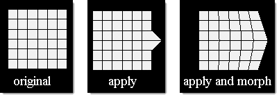
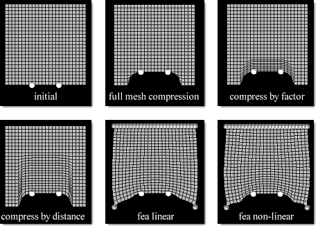
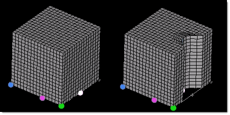
Examples:
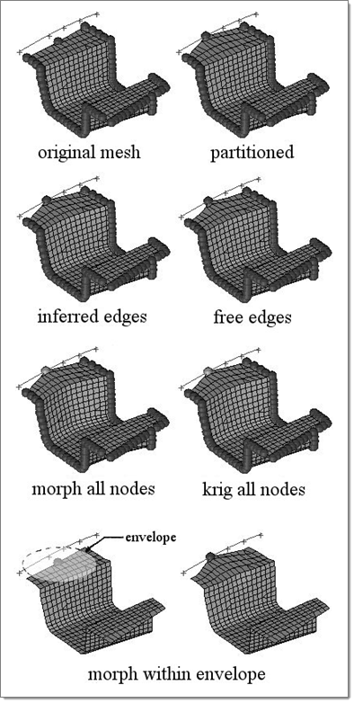
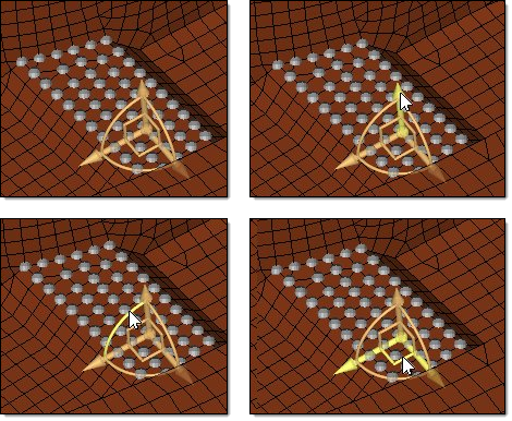
In the pictures above, note how the different methods affect the mesh morphing using the move nodes tool. For the partitioned option, the inner edge closest to the moved nodes is unaffected since an edge domain is internally created for it. For the inferred edges option, no inner edges were created and thus the inner edge ends up curved as its nodes follow the moving nodes. For the free edges option, no outer edges were created either and thus the outer edges end up curved as well as the inner ones. For the morph all nodes and krig all nodes options, note the differences in the methods, especially the smoothness of the kriging algorithm. For the morph within envelope option, note how the mesh inside the envelope is linearly perturbed relative to the distance from the moving node and that no fixed nodes are required.
|
(movement direction switch)
|
This switch displays during any "move to" type of morph. Use it to determine the direction that the affected nodes are projected.
| • | normal to geom - this option maps nodes to the selected geometry in a direction normal to the geometry (which may be a different direction for each node). |
| • | along vector - this option maps nodes in the direction specified by the vector. |
| • | normal to elems - this option maps nodes in a direction normal to the elements on which the nodes lie, which may be a different direction for each node. |
|
(movement type switch)
|
Click the first switch to choose the type of movement. This affects what additional inputs display on the subpanel.
Options include:
If you chose manipulator:
You may then click and drag one of the three arrows of the manipulator to translate the nodes, click and drag one of the three arcs of the manipulator to rotate the nodes about the center of the manipulator, or click and drag one of the three right angles of the manipulator to move the nodes in a plane.
The images below show a triad manipulator and where to click on it to translate it along a vector, rotate it about an axis, or translate it in a plane.
You may also select or unselect nodes while the manipulator is active, changing which nodes are affected by the manipulator. If no nodes are selected, the manipulator will disappear.
The position of the manipulator will be set at the center of the selected nodes unless an origin node has been specified, in which case the manipulator will remain at the specified node until the manipulator is moved. Selecting new nodes will update the position of the manipulator unless an origin node is specified. Selecting or updating an origin node will reposition the manipulator at the new node without morphing the model. An origin node is helpful when you wish to rotate entities about a given point.
The orientation of the manipulator will be aligned with the global axes by default. You may update the orientation of the manipulator to be aligned with a local coordinate system or to a specified vector or plane by using the toggles and selectors below the manipulator selector. Reorienting the manipulator in this way will not morph the model.
You may create more than one manipulator at a time by switching the toggle between single manipulator and multiple. When switched to multiple, clicking the new manip button will allow you to create a new manipulator by selecting one or more moving nodes. The different manipulators may have different selected entities and different parameters, and can be moved independently of one another. Moving a manipulator, clicking a manipulator, or simply moving the mouse over one of the manipulators will cause the panel to be updated to parameters for that manipulator, allowing you to change the parameters or the entities associated with them if you desire.
The manipulators can be set to be active or inactive by switching the toggle to either manip:active or manip:inactive. When active the manipulators will morph the model when moved. When inactive the manipulators will only change their own position and orientation when moved.
|
| • | translate: Apply a perturbation to affected nodes. |
| • | rotate: Apply a rotation to affected nodes. |
| • | move normal: the nodes will move in the positive normal direction of attached elements. For non-planar elements, the normal average is used. |
| • | move to vector: move affected nodes to a specified vector. |
| • | move to node list: move affected nodes to a spline curve defined by picking nodes in your model. |
| • | move to line: move affected nodes to a specified line or line list. |
| • | move to plane: move affected nodes to a specified plane. Use the plane and vector selector to define the desired plane, and place the base node where you wish its center to lie in the model. |
| • | move to surface: move affected nodes to a specified surface(s). |
| • | move to mesh: move affected nodes to a specified group of elements. |
| • | move to equation: Move the nodes to a path or shape defined mathematically. |
Type in a function F(xyz) or use the selector to choose from a variety of standard shapes (sphere, cylinder, and so on). The function may contain x, y, and z variables with the rest being numbers or expressions. If using the selector to obtain a function for a standard shape, you should replace constants a, b, c, r, and R with numbers. The surface defined when the function is set to zero will be used as the target surface for the mapping. Use the prev and next buttons to create additional pages for your function if there is not enough space in the first page.
| Note: | Due to the tightly packed nature of the panel, the (movement type switch) appears BELOW the equation switch, which may be confusing at first. |
| • | apply shape: If you choose apply shape, the moving nodes selector is replaced by a shape selector. This allows you to choose an existing shape that defines the node perturbations that you wish to apply. |
|
affected elements:
|
When you perform any freehand morph with some fixed nodes defined, use this collector to select affected elements.
The affected elements will morph to accommodate the movements of the moving nodes and the bounds imposed by the fixed nodes. The scope of their deformation is influenced by the edge bounding method chosen, the mv bias, and the fx bias. If you are using the morph all nodes, krig all nodes, or morph within envelope options, you do not need to select affected elements.
|
at origin / at system / at node
|
When using move to equation, this switch allows you to choose the start point for the function:
| • | at origin stars the function at the default global coordinate system's origin (0,0,0). |
| • | at node reveals a node selector, allowing you to pick a node to serve as the starting point. |
| • | at system reveals a syst selector, allowing you to pick a local coordinate system. Its origin serves as the starting point. |
|
calculate using: all elements / elems
|
When using move normal, use this toggle to use either all elements when calculating the normal direction or to use only the elements you select.
|
calculate using: averaged norms / smoothed norms/ cfd corners
|
When using move normal, this switch lets you define how the normal direction is determined.
| • | averaged normals defines the normal direction for each node as the average of only the elements touching the node. |
| • | smoothed normals calculates the average normal direction for all elements and then smoothes them so that transitions near corners are not abrupt. |
| • | cfd corners uses a sophisticated algorithm to smooth the normals for all the elements such that the elements will not get folded when their nodes are morphed. |
Examples:
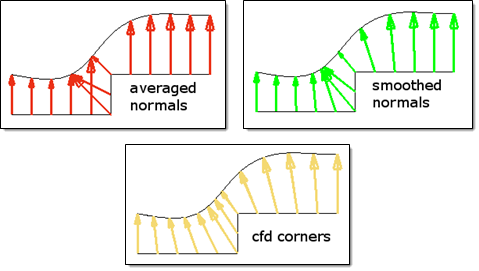
In the pictures above, note how the mesh (viewed in profile) is projected to a curved surface using each available option. For cases where your mesh contains sharp corners, the cfd corners option will produce the smoothest projections. However, it can be time consuming, and for meshes without such sharp corners the smoothed normals option will work quickly while giving good results. For a gently flowing mesh, the averaged normals option can also give a smooth final mesh.
|
deg
|
When you rotate, type the desired number of degrees to rotate the moving nodes into this numeric box.
|
dist=
|
When you select fix at distance, this field allows you to control the distance between the edge of the envelope and the moving nodes. Only nodes within the envelope will get morphed. Refer to the notes for fixed nodes for a full description of this feature.
|
dist /
X/Y/Z/syst
|
When you translate or move normal, this toggle allows you to define either the distance to translate (in model units) with the direction defined by the along plane & vector selector, or to defined the distance and direction via X, Y, and Z components (and optionally, a local coordinate system for the components.
|
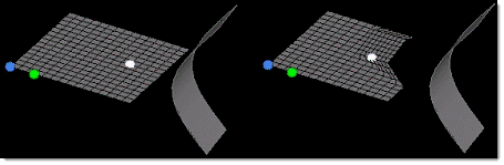
extend edges
|
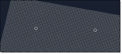
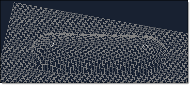
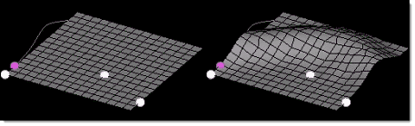
When using move to surf or move to mesh, the extend edges checkbox will appear, enabling you to extend the edges of the surfaces or mesh in a direction perpendicular to the normal at the closest point on the surfaces or mesh. If this checkbox is selected, the moving nodes will be projected on to an extended representation of the surfaces or mesh, enabling you to project nodes beyond the edge of the surfaces or mesh as well as within any holes. If this checkbox is not selected, the moving nodes will be projected on to the interior or edges of the surfaces or mesh, which may end up distorting the morphed mesh.
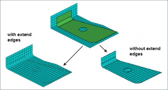
In the example above, three surfaces are floating above an angled mesh. All of the nodes of the mesh are selected as moving nodes and they are projected to the surfaces in the normal to geom direction. With extend edges selected, the moving nodes are moved either to the surfaces or to virtual surfaces which extend perpendicular to the normal direction at the edge of the surface. Note how the nodes end up placed inside the hole in the center of the largest surface. Without extend edges selected, the moving nodes are moved to the nearest point of the surfaces. Note how several layers of moving nodes end up compressed at the edge of the surfaces and around the edge of the hole.
|
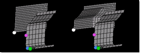
fixed nodes / fix unselected / fix ast distance / fix at multiple:
|
Use the selector to choose from the following options:
You will manually select which nodes will remain fixed during morphing. Nodes which are not selected as moving nodes or fixed nodes will be morphed based on how far they are between the nearest moving node and the nearest fixed node. The morphing applied to those unselected nodes will be based on the magnitude of the perturbation of the nearest moving nodes and reduced based on how close they are to the nearest fixed node.
All nodes which aren’t selected as moving nodes will automatically be fixed.
| Note: | This might result in sharp transitions between the moving nodes and the surrounding mesh. |
Type in a distance into the dist field. HyperMorph will automatically fix all nodes which lie at or outside that distance from the moving nodes. You are also able to select nodes within that distance to be fixed during the morphing.
Once the nodes outside the given distance are automatically fixed, this option will work identically to the fix nodes option, except when using the morph within envelope approach (see the edge bounding methods detailed below). The morph within envelope approach will create a virtual layer of fixed nodes at the specified distance around all of the moving nodes. Unselected nodes between the moving nodes and either this layer or the nearest fixed node (if selected) will be morphed proportionally based on the distances between the unselected nodes and the bounding entities. The difference between morphing within an envelope and morphing between moving and fixed nodes becomes clear when there are no fixed nodes near the moving nodes. In such a case, morphing within an envelope will always reduce the perturbations applied to the unselected nodes based on how far they are away from moving nodes, while the other methods will apply perturbations (and sometimes large ones) to all nodes which are not close to fixed nodes.
Type in a multiplier into the mult field. HyperMorph will automatically fix all nodes which lie at or outside a distance calculated by multiplying the perturbation of the nearest moving node by the given multiplier. You are also able to select nodes within that distance to be fixed during the morphing.
Once the nodes outside the calculated distance are automatically fixed, this option will work identically to the fix nodes option, except when using the morph within envelope approach (see the edge bounding methods detailed below). The morph within envelope approach will create a virtual layer of fixed nodes at the calculated distance around all of the moving nodes. Unselected nodes between the moving nodes and either this layer or the nearest fixed node (if selected) will be morphed proportionally based on the distances between the unselected nodes and the bounding entities. The difference between morphing within an envelope and morphing between moving and fixed nodes becomes clear when there are no fixed nodes near the moving nodes. In such a case, morphing within an envelope will always reduce the perturbations applied to the unselected nodes based on how far they are away from moving nodes, while the other methods will apply perturbations (and sometimes large ones) to all nodes which are not close to fixed nodes.
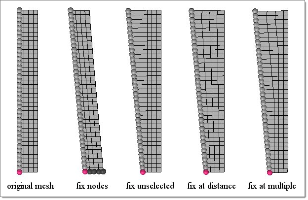
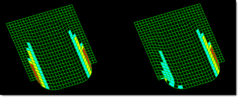
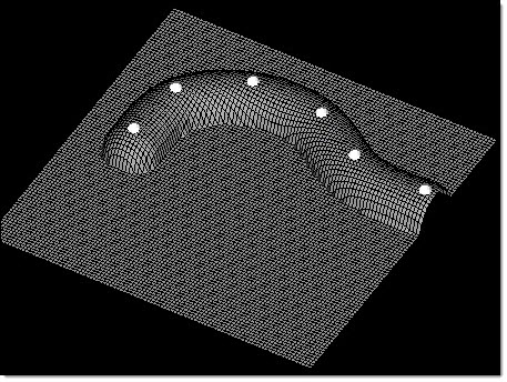
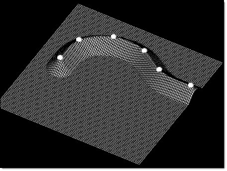
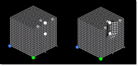
In the picture above, note the differences in the morphing due to the option selected for fixing nodes. When using the fix nodes option (with krig all nodes selected in the case shown), nodes far from the fixed nodes are morphed in a manner nearly identical to the nearest moving node. When using the fix unselected option, only the moving nodes are morphed. When using the fix at distance option (with morph within envelope selected), the morphing is spread linearly through the envelope based on how far away each morphed node is from the nearest moving node. When using the fix at multiple option (with morph within envelope selected), the morphing envelope is greater where the moving nodes move the farthest and thus those moving nodes have a larger affect on the mesh.
|
fx bias
|
This numeric box displays when you morph nodes with selected fixed nodes. It affects the behavior of the nodes to be morphed.
Higher values keep morphed nodes closer to the fixed nodes, reducing local distortion.
|
interactive: on/off
|
Switch this toggle to drag handles across the screen using the mouse after clicking morph. Morphing occurs in real time, rather than in a single "jump" based on input distances or angles upon clicking the button.
| Note: | When morphing by a manipulator (in version 12.0 SA110) all morphing is done interactively. |
|
moving nodes:
|
Pick the nodes that will move.
When using apply shape, this collector is replaced by a shape collector to allow you to pick an existing shape.
|
mult
|
When morphing by apply shape, this numeric box allows you to apply a multiplier to the effect of the shape. The default value of 1 uses the shape at its default size/strength, while higher numbers increase its effect on nodes and decimal values between zero and one decrease its effect.
|
mult=
|
When you select fix at multiple, this field allows you to control the distance between the edge of the envelope and the moving nodes. Only nodes within the envelope will get morphed. See the notes for fixed nodes for a full description of this feature.
|
mv bias
|
This numeric box displays when you morph nodes with selected fixed nodes. It affects the behavior of morphed nodes.
Higher values result in morphed nodes following the moving nodes more closely, reducing local distortion.
|
node a, node b
|
These two node collectors display when the (movement type switch) is set to move to vector. The target is defined as the vector from node a to node b.
|
offset=
|
When moving nodes to a vector, node list, line, plane, surface, or mesh you have the option of setting how far the nodes will be offset from the target. Although the nodes will be moved in the specified projection direction, the offset will be the absolute distance, in model units, the nodes will end up from the target regardless of the direction in which they were moved.
A positive value for the offset will place the nodes short of the target, a negative value for the offset will place the nodes beyond the target, and an offset of zero will place the nodes on the target.
|
offset in all dir. / offset along proj.
|
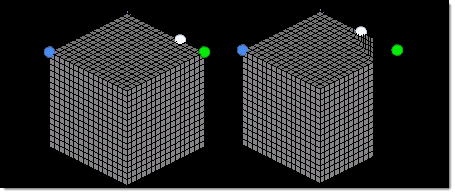
When moving nodes to a vector, node list, line, plane, surface, or mesh while using a non-zero offset, you may select offset in all dir, which will measure the offset from each node to the closest point on the target, or offset along proj, which will measure the offset from each node to the target along the direction of projection.
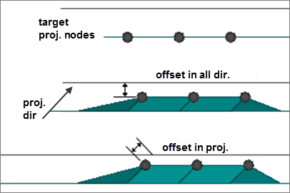
In the picture above, three nodes are being offset from a plane along a vector which is at a forty-five-degree angle to the plane normal. When offset in all dir is selected, the offset is measured from each node to the closest point on the target plane, in this case along the plane normal. When offset in proj is selected, the offset is measured from each node to the plane along the projection vector. Note that when using the offset in proj option, the nodes can end up closer to the nearest point on the target than the value of the offset.
|
optional fixed nodes
|
Add any fixed nodes inside the envelope to be used for morphing. The morphing of any nodes near these fixed nodes will be reduced.
|
options
|
Opens the morph options panel.
|
rotate about
|
Use the standard plane & vector selector to define an axis around which to rotate the moving nodes.
|
|