|
»Click here to display Table of Contents«
|

Meshless Welds Macro |

|

|

|

|
|
Meshless Welds Macro |
|
|
|

|
|
»Click here to display Table of Contents«
|
Meshless Welds Macro |
|
|
|
|
|
Meshless Welds Macro |
|
|
|
|
The RADIOSS Meshless Welds macro is accessible through the Tools page on the RADIOSS Utility menu.
When you select the Welds button, the following dialog is displayed:
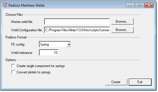
This macro allows you to create meshless welds for RADIOSS using /SPRING elements and /INTER/TYPE2 to connect the shell together. Additionally, a /PROP/SPR_BEAM with user-defined custom properties is created. The macro identifies the current template and creates welds for both RADIOSS (Fixed Format) or RADIOSS models.
To use the Meshless Welds macro:
| 1. | Select a master weld file to define the weld locations. This file must contain the coordinates of the weld points and the component IDs of connected parts. Weld files can be written out by exporting connectors in the Export tab. |
| 2. | Select the spring property file. |
| 3. | Specify the Spring FE config and an appropriate weld search tolerance. |
| 4. | Click create. |
Meshless welds are created and grouped into components based on the parts to which they are attached and the property of the spring is created according to the strength of attached parts. INTER/Type2 interfaces are created. Plot elements are created to facilitate the review of meshless welds and attached components. These plot elements connect the welds to corresponding parts.
You can select one of the following options:
| • | Activate create single components for spring to store all the /SPRINGs into the same component. |
| • | Activate the Convert plotels to spring to replace the default HMPLOT element (not supported by RADIOSS) into a /SPRING element that can be imported back into the program and used together with find attached. |
Weld tolerance is used in the connector search algorithm to identify welds and attached parts.
The spring property file defines the data to be used in computing spring properties for RADIOSS beam type springs /PROP/SPR_BEAM. The sample file, Radiossweld_config.ini, is stored in the hm\scripts\connectors directory of the Altair installation and its format is shown below.
Radiossweld_config.ini n the hm\scripts\connectors\
# HWVERSION_11.0
Variables |
|
MASS |
0.002 |
Inertia |
0.1 |
K1 |
100.0 |
K2 |
500.0 |
K3 |
500.0 |
K4 |
5000.0 |
K5 |
5000.0 |
K6 |
5000.0 |
Delmin1 |
-1.25 |
Delmax1 |
1.25 |
Delmin2 |
-1.25 |
Delmax2 |
1.25 |
Delmin3 |
-1.25 |
Delmax3 |
1.25 |
Delmin4 |
0.0 |
Delmax4 |
0.0 |
Delmin5 |
0.0 |
Delmax5 |
0.0 |
Delmin6 |
0.0 |
Delmax6 |
0.0 |
End |
|
# Normal Force Function
CVID1 |
9 |
|
|
-100.0 |
0.0 |
|
-1.26 |
0.0 |
|
-1.25 |
-Fn |
|
-0.125 |
-Fn |
|
0.0 |
0.0 |
|
0.125 |
Fn |
|
1.25 |
Fn |
|
1.26 |
0.0 |
|
100.0 |
0.0 |
# End Normal Force Function
# Shear Force Function
CVID2 |
9 |
|
|
-100.0 |
0.0 |
|
-1.26 |
0.0 |
|
-1.25 |
-Fs |
|
-0.125 |
-Fs |
|
0.0 |
0.0 |
|
0.125 |
Fs |
|
1.25 |
Fs |
|
1.26 |
0.0 |
|
100.0 |
0.0 |
# End Shear Force Function
Generic Spot Weld Failure Force Table
Sheet metal gauge in mm |
Shear force |
Normal force |
|
T > |
T =< |
Fs[kN] |
Fn[kN] |
Steel YS < 120 MPa |
|
||
~ |
0.6 |
2.7 |
0.9 |
0.6 |
0.8 |
3.6 |
1.2 |
0.8 |
0.9 |
4.4 |
1.5 |
0.9 |
1.0 |
5.3 |
1.9 |
1.0 |
1.1 |
6.2 |
2.2 |
1.1 |
1.3 |
7.1 |
2.5 |
1.3 |
1.4 |
8.0 |
2.8 |
1.4 |
1.5 |
9.1 |
3.2 |
1.5 |
1.8 |
11.1 |
3.9 |
1.8 |
2.0 |
12.5 |
4.4 |
2.0 |
2.3 |
15.1 |
5.3 |
2.3 |
2.7 |
18.2 |
6.4 |
2.7 |
~ |
21.8 |
7.6 |
Steel1 YS = 120to220 MPa |
|
||
~ |
0.6 |
2.7 |
0.9 |
0.6 |
0.8 |
3.6 |
1.2 |
0.8 |
0.9 |
4.4 |
1.5 |
0.9 |
1.0 |
5.3 |
1.9 |
1.0 |
1.1 |
6.2 |
2.2 |
1.1 |
1.3 |
7.1 |
2.5 |
1.3 |
1.4 |
8.0 |
2.8 |
1.4 |
1.5 |
9.1 |
3.2 |
1.5 |
1.8 |
11.1 |
3.9 |
1.8 |
2.0 |
12.5 |
4.4 |
2.0 |
2.3 |
15.1 |
5.3 |
2.3 |
2.7 |
18.2 |
6.4 |
2.7 |
~ |
21.8 |
7.6 |
Steel3 YS = 221to500 MPa |
|
||
~ |
0.6 |
4.9 |
1.7 |
0.6 |
0.8 |
6.7 |
2.3 |
0.8 |
0.9 |
8.5 |
3.0 |
0.9 |
1.0 |
10.2 |
3.6 |
1.0 |
1.1 |
12.0 |
4.2 |
1.1 |
1.3 |
13.8 |
4.8 |
1.3 |
1.4 |
15.6 |
5.5 |
1.4 |
1.5 |
17.8 |
6.2 |
1.5 |
1.8 |
21.8 |
7.6 |
1.8 |
2.0 |
25.0 |
8.8 |
2.0 |
2.3 |
31.1 |
10.9 |
2.3 |
2.7 |
38.7 |
13.5 |
2.7 |
~ |
44.5 |
15.6 |
Steel4 YS > 500 MPa |
|
||
~ |
0.6 |
4.9 |
1.7 |
0.6 |
0.8 |
6.7 |
2.3 |
0.8 |
0.9 |
8.5 |
3.0 |
0.9 |
1.0 |
10.2 |
3.6 |
1.0 |
1.1 |
12.0 |
4.2 |
1.1 |
1.3 |
13.8 |
4.8 |
1.3 |
1.4 |
15.6 |
5.5 |
1.4 |
1.5 |
17.8 |
6.2 |
1.5 |
1.8 |
21.8 |
7.6 |
1.8 |
2.0 |
25.0 |
8.8 |
2.0 |
2.3 |
31.1 |
10.9 |
2.3 |
2.7 |
38.7 |
13.5 |
2.7 |
~ |
44.5 |
15.6 |
The values of relevant variables are defined in the first section and these values are copied directly onto the RADIOSS spring property cards.
The second and third sections define the normal and shear force functions with nine data points. Based on the strength of the connected components, the Weld macro calculates appropriate force function for each weld. Except for the value of Fn and Fs, the data points remain constant and equal to the values defined in the normal and shear force functions. Force function defines deformation vs force values as required by RADIOSS.
Finally, the last section contains the force tables as a function of yield stress of the material. You can enter any number of tables into this section. Each table identifies the yield strength of the material and the normal and shear force of the weld corresponding to the thickness range.
During the macro execution for every weld the macro identifies the connected parts and for each part, the macro extracts the corresponding shear and normal force from these tables based on the part thickness and material yield strength. The lowest shear and normal force of each weld is identified by comparing the force values of the attached components and is used in the spring property definition of the weld.