Location: connectors module
The Apply Mass panel is an unusual usage of connector entities in that it does not create a physical join/connection. Instead, the connector entity is used to distribute mass to nodes or elements. This can be done using different methods (mass types). You can create a point mass to represent a part that does not exist in the model (such as a door-mounted speaker) or you can distribute several single-point masses to change the mass of an entire region in the model. You can also create non-structural masses.
The mass which has been applied by each connector can be shown in the connector list of the Connector browser. (You may need to activate the mass column in the Configure browser window first.)
| Note: | The mass column doesn’t differentiate between mass, mass per length, and mass per area. |
|
When the Apply Mass panel is active, only mass-type connectors display in the graphics area; graphics for other connector types are suppressed until you exit the panel.
Panel Usage
There are no subpanels on the Apply Mass Panel. All creation and edit options can be performed from the main panel.
Panel Input fields are arranged into two columns by default: the first column includes options to specify the location and connection rules of the connectors, while the second column defines the mass type. A series of command buttons on the rightmost edge of the panel allow you to create or edit mass connectors, reject an erroneous creation or edit of mass connectors, or exit the panel.
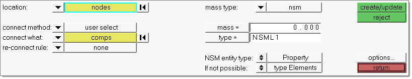
Panel Inputs
Input
|
Description
|
location
|
The FE or geometric entities to which the mass connector entities are created. Use the switch to choose between valid options:
|
Connector entities are created at the locations defined by selected FE nodes.
|
|
Connector entities are created at the locations defined by selected geometry points.
|
|
Mass is applied to existing connector entities, allowing you to update applied masses by updating the connector.
|
|
connect method:
|
Only available when the location is nodes or points, this switch lets you choose the method to determine which entities the mass connector connects.
|
Connects the entities to any entities of the location type within the search tolerance.
|
|
Select specific entities manually. This changes the connect what field (see below) into a selector with a switch, rather than a label with a switch.
|
|
connect what:
|
Only available when the location is nodes or points, this field lets you choose what type of entity the mass gets applied to:
|
The mass is applied via nodes. When this option is chosen, nsm becomes unavailable in the mass type field (see below).
|
|
The mass is applied to the nodes of elements.
|
|
The mass is applied to the nodes of entire components.
|
|
The mass is applied to nodes via their tags.
|
|
Select the assemblies to be added as link entities.
|
|
Elems to current comp / Elems to connector comp
|
This toggle only displays when the location is set to connectors, and determines which component the connectors are stored in once they have been realized.
| Note: | Connector types that use a property script, such as Mat100, ACM, or Type2 (RADIOSS), may override this setting and place the connectors into components based on script settings. |
|
Newly generated mass elements become part of the current component (displayed in the status bar).
|
|
Newly generated mass elements from a connector become part of the same component that the connector belongs to.
|
|
search tol =
|
When searching for connection points between the connect what entities, HyperMesh uses this value as a limiter on how far away from the chosen location a connection can be made.
|
limited to entities
|
This is an advanced filter to determine the number of entities to include for the applied mass. Picking a number from this switch limits the total number of components that the new mass entity will apply to, even if the search tol is high enough to select more components (or even the entire model). HyperMesh chooses the closest component(s) to the mass connector until this limit is reached.
Note: This setting only takes effect if the checkbox is active.
|
|
Input
|
Description
|
mass type
|
Use this switch to choose between different mass configurations:
|
The mass is a non-structural mass and defines/updates the required solver cards.
Currently this is only available for OptiStruct and Nastran. A group entity is created for each connector when realizing this connector type. The group gets a NSM1 or a NSML1 card assigned.
The group references all in the connector-linked elements. These linked elements include elements from direct element links, but also the elements belonging to a component or assembly link. The NSM entity type attribute decides whether the reference is realized via a simple element list, or the reference is realized via a property list (of a certain type). The property reference requires clear properties, which exactly condense the elements linked in the connector.
|
|
The mass is a single mass element created at a node.
|
|
The mass takes the form of a mass element connected to nodes with rigid elements (multiple RBE2).
|
|
The mass takes the form of a mass element connected to nodes with a rigidlink element (single RBE2).
|
|
The mass takes the form of a mass element connected to nodes with a RBE3 element.
|
|
mass
|
This value is the amount of mass you wish to add. However, it works differently depending on the choice for distribution (se below). In some cases it is the total mass, while in other cases it is the mass per node or mass per unit of area (such as square millimeter).
|
type
|
This field is only available when mass type is set to nsm. The solver card to be created is defined here.
|
NSM entity type
|
The connector to be created gets an NSM entity type attribute. It is written into the connector and is considered during the next realization.
Upon creation of nsm connectors, the FE data (nsm group entity) is realized and a new component (CE_Mass_inc_<include name>) is created inside the current include. The newly created connectors will reside in this new component. Each include is meant to host its own CE_Mass_inc_<include name> component, and HM will produce a warning if the component name already exists in a different include. This helps ensure that unrealizing and rerealizing nsm connectors will keep the FE data in its original include.
The realization routine always looks for the content (elements) of the links and investigates whether they exclusively reference the same properties (direct or indirect) and can be condensed clearly in property references in the NSM group.
The realization can behave differently depending on this check and the defined NSM entity type attribute.
Three different attributes can be set to the connectors.
|
The realization creates one element based NSM group for each connector. All of the connector-referenced elements are listed by ID in the created NSM group.
|
|
The realization creates one NSM group per connector.
If all in the connector-referenced elements can be exclusively condensed in clearly defined properties, theses properties are used for the property-based NSM group.
See below for the cases where this is not possible.
|
|
Sometimes it is not possible to identify exclusive properties for a clear realization as property based NSM groups. For those cases the following sub-attribute decides how to proceed with the realized connectors.
type elements
|
If this sub-attribute is set, the realization creates an element-based NSM group instead.
|
fail connector
|
If this sub-attribute is set the realization fails.
| Note: | After a sufficient reorganization of the properties, a successful realization as a property-based NSM group might become possible. |
|
|
|
distribution
|
This switch only displays when the mass type is set to point mass. Use it to determine how to apply the amount specified in the mass= field to the affected location’s nodes. The examples shown below all use a 9-node array with a 100mm x 100mm area (for example 10,000 square mm) and a mass of 10 grams:
|
The mass is applied repeatedly, once to each node (so the total mass applied is the mass times the number of nodes).
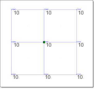
The mass (10) is applied to each node.
|
|
The mass is divided by the number of nodes, and the result applied to each node.
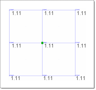
The mass (10) is divided among the 9 nodes.
|
|
This option only displays when the connect what option is not set to nodes.
Similar to divide mass by nodes, this divides the mass= value among the affected nodes. However, this method ensures that non-uniform meshes still produce uniform mass distribution. It does this by:
| 1. | Determining the mass per unit of area (in this example, 10g/10,000mm=0.001g/sq. mm). |
| 2. | Determining the area of each element (in this case, all of the 4 elements are 50x50=2500 sq. mm). |
| 3. | Multiplying the per-unit mass by the number of units per elem to find each element’s total mass. (.001x2500=2.5g per elem in this example). |
| 4. | Dividing the elem’s mass by the elem’s number of nodes (yielding 2.5/4=0.625 per node in this example). |
| 5. | Nodes belonging to more than one element receive a per-node mass from each element accumulatively. |
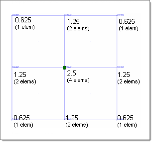
In this example, each node receives 0.625g
from each element that it belongs to.
|
|
This option only displays when the connect what option is not set to nodes.
This option is similar to divide mass by area except that the full mass= value is applied to each square unit of the selected area. Then this mass is distributed across the area as for divide mass by area (steps 2+). In other words, this follows the same steps as described for divide mass by area with the omission of step 1, so that the full mass= value is used as the per-unit mass.
Thus, in this example each node receives 6,250 grams from each element that it is a part of:

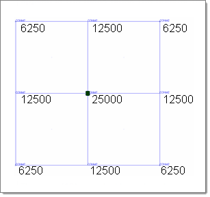
This method produces an area-based distribution
but with much higher masses.
|
|
|
The following action buttons appear:
Button
|
Action
|
create/update
|
Create a new mass connector entity (or entities) with the specified settings, if sufficient. Alternatively, update an existing connector (if selected as the applied mass location).
|
reject
|
Undo the applied mass creation or update.
|
return
|
Exits the Apply Mass panel.
|
|
See Also:
Connector Definition
Connector Realization
Connectors Module
An Alphabetical List of HyperMesh Panels


