HyperMesh and BatchMesher

seam panel

seam panel

Previous topic Next topic Expand/collapse all hidden text  

seam panel

Previous topic Next topic JavaScript is required for expanding text JavaScript is required for the print function  

Location:   connectors module


Use the connector Seam panel to create connectors that represent line connectors such as seam welds.  These connectors can later be realized as standard or custom weld representations.

When the Seam panel is active, only seam-type connectors display in the graphics area; graphics for other connector types are suppressed until you exit the panel.


Panel Usage


Each type of edit option for seams is arranged into its own subpanel. You can move freely between subpanels--your work on one subpanel will not be lost if you switch to a different subpanel, then return.  However, similar settings will not be shared between subpanels, so for example changing the tolerance in one subpanel does not change it in any of the others. In most cases one or more green command buttons on the right edge of the subpanel must be used to execute the function once all options have been specified.

Set the panel mode by selecting the subpanel appropriate to the type of edit you wish to perform.
In the subpanel, choose input options to characterize new seams, or edit existing ones.

connector_seam_seam_panel


Subpanels and Inputs


The Seam panel contains the following subpanels and command buttons:

Seam: The seam connector is both created and realized in one shot.
Create: The seam connector is created only--no realization occurs on this subpanel.
Realize: An existing seam connector is realized only--no creation options exist on this subpanel.
Edit: An existing seam connector gets edited.
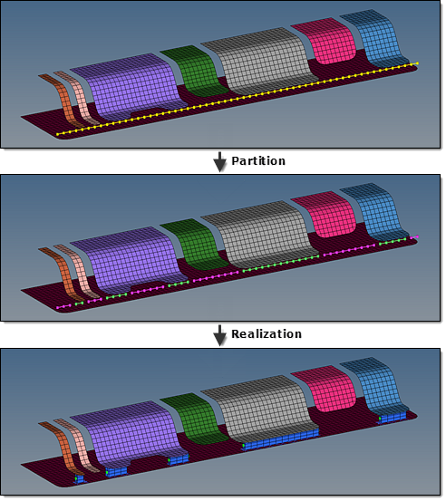
Partition: An existing seam connector gets partitioned--that is, seams are separated into sections of connections that passed or failed valid projections.
hmtoggle_arrow1See more details.

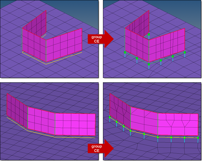
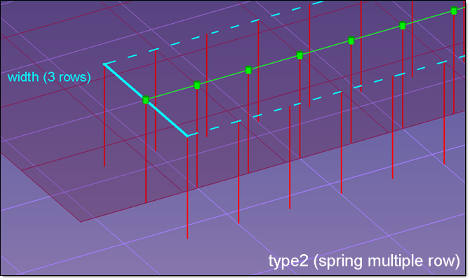
Increasingly often the location of a seam is given by the welding or gluing robot path as a geometrical line. These lines are mostly continuous lines even though the robot doesn’t weld or glue on a line's entire path. As a result, connectors based on these kinds of lines contain sections where a valid projection to at least two links is not possible.

The seam partition functionality has the capability to identify these sections without valid projections. For each point along the seam the availability of two valid projections onto link candidates with respect to a user-specified tolerance is identified. At each position where a point with valid projections follows on a point with invalid projections or vice versa, the connector is partitioned.

The picture below shows a long, straight seam with all shell components defined as link candidates. After partitioning the seam is separated into "passed" and "failed" connector sections. In the picture the connectors are shown in their component color; in mint green (passed) and magenta (failed). The subsequent realization can easily be performed on all passed connectors.

connector_seam_partition_example

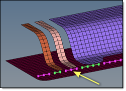
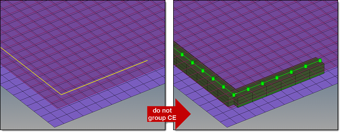
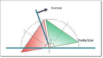
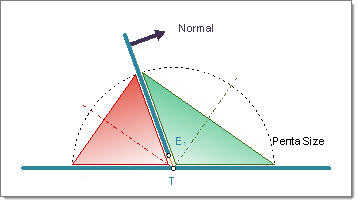
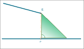
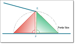
The default projection test is a normal projection considering the tolerance, so the failures in the example above are mostly obvious--either the projections cannot be done at all, or the distance is too great.

If there is only one point with valid projections in between two points without valid projections, the one is also marked as failed. This is because a seam needs to consist of at least two points. See picture below as an example.

connector_seam_partition_example2


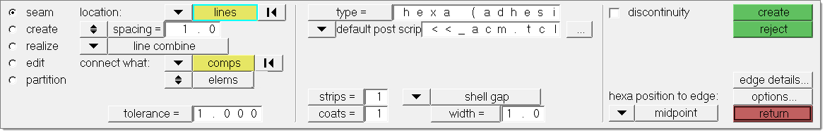
The seam, create and realize subpanels use the same set of entry controls. They are organized in three different columns:

1.The first column contains everything related to connector creation and link detection.
2.The second column contains everything related to realization type, post script and property assignment.
3.The third column contains everything related to the final connection to the link entities.


These columns and their organization are illustrated in detail in Connector Panel Structure in the Connectors chapter.  See Special Realization Types in the Connectors chapter for further information on specific realization types.

From the seam panel you also have direct access to the Connector Options panel, where general and connector type-specific settings can be set. In particular, settings which don’t need to be altered very often are provided there.


Panel Input


hmtoggle_arrow1Inputs for Connector Creation and Link Detection

Input

Description

location

Specify the location of the connector to be created by selecting one of the following:

lines/line list

Select lines and specify spacing or density.

If you select several lines, HyperMesh determines whether lines share the same start- and endpoints or not. This means, HyperMesh is able to determine if certain groups of lines can principally be combined into one line.

How this information is used during connector creation depends on the options line combine, group CE, and do not group CE. See the descriptions below.

node list

Select a node list and specify spacing or density.

The selected nodes are used to internally create a smoothed line, which is used exactly as a real line. The connector will not remember the position of the selected nodes, unless you select the preserve nodes check box.

You can only create one seam connector at a time using a node list.

When you are selecting a node list, and the first and last node belong to the same element, HyperMesh will create the connector as a closed loop.

spacing/density

Distance between each weld location on the line (spacing), or number of weld location on the line (density).

retain nodes

Retains the position of the nodes when you create and realize a connector.

This check box is only available if the location is defined by a nodelist.

connectors

Specify the seam connectors to be realized.

line combine

Creates one seam connector for each sequence of lines and each single line. With this option active, a sequence of lines will be internally treated as on line. This is the default setting.

This option is preferred for continuous seams together with realization types where the body element is positioned between the weld points like for all quad and hexa seam realizations.

seam_panel_linecombine

Note:With this option, neither the vertices nor the start- and end- points of the initial lines are considered, and there likely will not be any weld points at the exact positions.

seam_panel_linecombine2

group CE

Creates one seam connector from each selected line, and groups those seams which form a sequence of seam connectors together. Each group of connectors is then treated as a single connector entity: each connector in the group has the same display mode, same realization state, and so on. Furthermore the start- and end- points of two sequenced connectors in that group are treated as being one point. This fact allows this option also to be used together with realization types where the body element is positioned between the weld points, like for all quad and hexa seam realizations. For hexa seams and for use of quad transition, the vertex angle has to be quite small to prevent bad hexa elements or imprint conflicts.

seam_panel_group_CE

Note:The selected lines need to be longer than half the spacing length, otherwise the lines are ignored.

do not group CE

Creates one seam connector from each selected line. Even those seams which form a sequence of seam connectors are not grouped together. The start- and end- points of two sequenced connectors in that group are treated as being different points. This fact makes the use of quad transition impossible for sequenced seam connectors, because the imprint patterns will always conflict each other. This option is mainly used for situations like the one shown below:

seam_panel_donotgroup_CE

Note:The selected lines need to be longer than half the spacing length, otherwise the lines are ignored.

connect what

Select the entities, which should become link candidates. Link candidates are certain entities of a chosen Link Type, which are supposed to be connected during the realization. Entities outside the tolerance are not taken into account

comps

Select the components to be added as link entities.  You can choose to connect to either the geometry or elements of the selected components.

assems

Select the assemblies to be added as link entities. You can choose to connect to either the geometry or elements of the selected assemblies.

surfs

Select the surfaces to be added as link entities.  You can choose to connect to either the geometric surfaces or elements associated to the selected surfaces.

Note:Connectors can be created with different types of entities; for example, a connector can be defined by selecting a component on one side and an assembly on the other side.  This can be done by creating a seam connector to specify one of the entity types and selecting that entity. Add the second entity by updating the connector via the add links functionality in the Connector browser or the Add Links panel.

num layers

Defines how many thicknesses (layers) have to be connected at the connector position. This number is predefined as two for seams, so there is not any field in the Seam panel where you can set the number of layers; however, you can find the number of layers in the Connector browser for seam connectors.

When the link detection is performed the valid connector links are established with respect to the given tolerance and the selected link candidates. By default the links are reduced to the minimum needed ones. Typically for seams the number of links is higher than the number of layers, because a valid pair of projections need to be found per test point.

See also Link Conservation in the Connector Options panel.

tolerance

Defines a distance from the connector location (per each test point). Only entities within this tolerance can be taken into account for the link detection and the final realization. Thus, the tolerance is used twice: first for the link determination and again for the realization. In the second step the tolerance is used to verify whether adequate link candidates are available to be connected.

During pure connector creation on the Create subpanel, the tolerance is used for the link determination, but not necessarily stored on the connector unless the checkbox in front of the tolerance field is marked. In this way different tolerances can be used.

The tolerance used during the realization process is always written to the connector.

connect when

Defines when to perform link detection.

now

Adds link entity information now, directly together with the connector creation.

at fe-realize

Creates a connector without any specific information regarding its links. The links are determined when performing the final realization with respect to the connector position.

Using this option defines the Reconnect rule as "at fe-realize" for all created links.

reconnect rule

none

No re-connect rule is defined.  If the link entity is not currently in the model, the connector with this re-connect rule will fail to realize.

If no re-connect rule is defined for a link, this link disappears from the connector, when the linked entity is deleted.

use id

Use the selected link entity’s IDs to re-connect.  If the link entity is not currently in the model, the connector with this re-connect rule will search for entities with the same ID.

use name

Use the selected link entity’s names to re-connect.  If the link entity is not currently in the model, connectors using this re-connect rule search for entities with the same name.

reverse direction

During the first realization of a seam its direction is determined. Even though this direction is only important for realization types which use angle information like seam-quad (angled), every seam gets this direction. Therefore the reverse direction checkbox only appears for angled seams.

The direction can only be reversed during the next realization if the checkbox is marked.

Note: Normally this option is only needed for T-welds, because in that case there isn’t any indication for the probable direction.

For this reason, if an angled T-weld should be realized together with quad transition, it might be useful to skip the imprint in the first step and review the assumed direction. Rerealize all wrong directed seams with the checkbox marked. If all directions are correct, uncheck the option and rerealize with active imprint. This procedure prevents the mesh from being interfered more often than necessary.


hmtoggle_arrow1Inputs for Post Script and Property Assignment

Input

Description

type

Identifies the realization type which should be used for realization. Which realization types are listed here depends on the configuration file loaded under fe file on the general options subpanel of the Connector Options panel.

The realization type is a description of the FE representation. The provided list depends on the active user profile.

Post Script Treatment

Specifies whether or not a post script has to be used for the specific realization type. These scripts are used to automatically create materials, properties, and/or contacts necessary for realizing the connectors.

default post script

Default for any realization type having a post script defined in its FE configuration.

user post script

Specify your own TCL file which should be used. Such a file can perform a special treatment on the FE representation

no/skip post script

Default for all realization types without any post script defined. No post script is used.

elems to current comp / connector comp

Determines which component the FE representations are stored in once they have been realized.

current comp

Newly-realized connectors become part of the current component (displayed in the status bar).

connector comp

Newly created FE representations become part of the same component that the connector was originally created in.

This toggle only displays on the realize subpanel if no/skip post script is used.

property treatment

Specifies whether or not a certain property gets assigned.

property

Select a pre-defined property to assign to all newly created elements.

no property

No property gets assigned to all newly created elements.

This option only displays if no/skip post script is used.

direct property assignment

Assigns the property directly. If this check box is cleared, the property is assigned to the destination components.

This option only appears when when the property treatment property = is chosen and the user profile is Nastran, OptiStruct, RADIOSS or Abaqus.


hmtoggle_arrow1Inputs for Specific Realizations

The following settings are exclusively available for seam realization types with a quad row representing the connection. Not necessarily all of these settings have to be defined for all quad realization types. Below are examples of the more complicated ones.

adj1

Input

Description

weld angle

The weld angle is measured between the normal projection and the quad direction. See the pictures above.

Principally it is allowed to define weld angles between 0.0 and 90.0. If the value is set to 0.0 an internal thickness-based calculation is used. If the value is set to 0.0 and no thickness is defined the connector will fail.

If the angle is created in the wrong direction, the seam can be reverted by activating the reverse direction checkbox and performing a rerealization.

cap angle

The cap angle is measured in two different ways depending on the seam-quad type (see the pictures above):

between the normals of the cap element and the second-to-last element of the seam,

or

between the edge normals of the cap element and the second-to-last element of the seam in the plane of the opposite link.


Cap angles are created by default. Clear this check box to remove cap angles and runoff angles.

Cap angles between 0.0 and 45.0 are permitted, but be aware that larger values can lead to bad elements. The recommended value is 10.0 or smaller. Cap angles between 45.0 and 90.0 are permitted, but be aware that smaller values lead to bad elements. The recommended value is 75.0 and higher.

Only available for seam-quad (angled + capped + L) and seam-quad (angled + capped + T).

runoff angle

The runoff angle is measured in two different ways depending on the seam-quad type (see the pictures above):

between the normals of the last and the second-to-last last element of the seam,

or

between the edge normals of the last and the second-to-last element of the seam in the plane of the opposite link.


Clearing the cap angles check box removes runoff angles, which are created by default.

height

The height is exclusively available for the T-seam shown above. It’s measured between the projection point and the start-point of the angled quads.

Note:The height needs to be chosen in an extent to bridge the gap between the links. Also, the height strongly influences the quad length, especially in cases of very large weld angles.


The following inputs are available for seam realization types with hexa row(s) representing the connection.

seam_panel_realization_with_hexas

Input

Description

width

Defines the width of the continuous hexa weld in the direction perpendicular to the seam direction.

Only available for hexa (adhesive) and hexa (RBE2-RBE3).

strips

Defines the number of hexa elements required along the width.

coats

Defines the number of hexa elements required along the thickness.

thickness

Use the following settings to define the thickness of a hexa weld.

shell gap

With this option the hexa seam will project and be touching the shell elements.

The position is independent from any thickness.

(T1+T2)/2

With this option the hexa seam size (thickness) depends on the shell thickness of the connected parts.

mid thickness

With this option the hexa seam size (thickness) is calculated as the air gap between the two connected parts. If there is no gap, or even a penetration, the hexa seam size is always modeled with 1.0.

const. thickness

With this option the hexa seam size (thickness) is directly specified by giving the value.

maintain gaps

With this option the hexa seam size (thickness) is calculated as the gap distance reduced by two times the specified value for maintain gaps.

The position is independent from any thickness.

Note:The exact hexa position is also influenced by the consider shell thickness and offset for solid positioning option. See hexa positioning for hexa adhesives and ACMs.

seam_panel_realization_with_hexas_shellthickness

Only available for hexa (adhesive) and hexa (RBE2-RBE3).

thickness dependent / angle, D and H / H1, H2 and D

Hexa (tapered T) enables you to create tapered seam hexas for T-connections.

To define how hexas are positioned and located, select one of the following settings and assign appropriate values to any corresponding inputs.

thickness dependent

connector_hexa_tapered_t_thickness_depent

tmin=  min(t1;t2)
d=  factor_a * tmin
h1=  factor_b + 2.5 * t2
h2=  factor_b + 2.5 * 211
angle, D and H

connector_hexa_tapered_t_angle_d_h

angle        =  angle to the base sheet α

d        =  thickness of hexa

h        =  height from the basesheet

H1, H2 and D

connector_hexa_tapered_t_h1_h2_d

h1        =  distance on T sheet

h2        =  distance on basesheet

d        =  thickness of hexa

Discontinuity

By default, the length and pattern of a hexa weld is defined by test points along the seam connector. To ignore the predefined test points, and define a specific element length, weld length, and break length to realize the connector with, select the discontinuity check box. With this option, a hexa adhesive seam with alternating weld pieces and gaps is created. This option is only available for hexa (adhesive) realizations, and is inactive by default.

When discontinuity is selected, you must define the following inputs:

elem length specifies the length of a hexa along the seam connector.
weld length/scale (elem) specifies the length of the hexa weld.
break length/scale (elem) specifies the amount of space to place in between the hexa welds.


If the defined lengths does not fit exactly to the seam connector length, mathmatical correct rounding is used. To guarantee, that the rounded lengths are not too far away from the expected values, minimum and maximum deviations are defined in the seam options.

hexa position to edge

Specify where to create the hexa from the edge:

midpoint positions the hexa to the exact location of the connector after snapping
offset from edge enables you to define a distance from the edge to offset the hexa
positive edge positions the hexa to the outside of the edge. The positive side is normally the side with the larger angle.
negative edge positions the hexa to the inside of the edge. The negative side is normally the side with the smaller angle.

The angle that is close to 90° (88° to 90°) the element normal of the first found shell element at the free edge decides which side is the positive and the negative side.

Only available for hexa (adhesive) and hexa (RBE2-RBE3).

edge details

In many cases, the connector position is not very precise. To create the requested result, an automatic edge snapping can be activated. In the first step the connector snaps to, for example, the closest free edge, and then from there the projection and FE creation starts.

Specify how many element rows away from the free edge to snap the connector to for L and T connections. Select whether to snap to:

maximum 1 element row
maximum 2 element rows
no (connector does not snap)


seam_panel_realization_with_pentas

Input

Description

width

Specifies the length of a penta.

Available for: penta (mig), penta (mig + L), penta (mig + T), and penta (mig + B).

fitted/equilateral/equilateral-fitted

Defines the size and shape of a penta.

Available for penta (mig) and penta (mig + L).

fitted

the length of one penta edge is the exact projection distance, and the length of the other penta edge is defined by the width value; the penta has an right-angle.

connector_penta_mig_l_fitted

equilateral

creates an equilateral penta; leg lengths are defined by the width value.

connector_penta_mig_l_equilateral

equilateral/fitted

combination of fitted and equilateral; you do not need to define a width when you select this option.

connector_penta_mig_l_equilateral_fitted

right-angled

Creates a right-angled penta that is oriented around the bisector. If this check box is cleared, an angle adapted penta will be created.

Available for: penta (mig) and penta (mig + T).

connector_penta_mig_t_right_angle

Right-angled T-weld penta created on both sides of the normal.

connector_penta_mig_adapted_angle

Angle adapted T-weld penta created on both sides of the normal.

both sides/positive sides/negative sides

Specifies which side of the normal to create the penta on.

Available for: penta (mig), penta (mig + L), penta (mig + T), and penta (mig + B).

(mig + L)

The negative side is the side where the links are fairly parallel to each other. The angle that is close to 90° (88° to 90°) the element normal of the first found shell element at the free edge decides which side is the positive and the negative side.

penta_mig_l_one_sides

Penta (mig+L) one side

penta_mig_l_two_sides

Penta (mig+L) two side

(mig + T)

The positive side is normally the side with the obtuse angle. The angle that is close to 90° (88° to 92°) the element normal of the first found shell element at the free edge decides which side is the positive and negative side.

penta_mig_t_one_side

Penta (mig+T) one side, positive side

penta_mig_t_two_side

Penta (mig+T) two side, positive and negative side

(mig + B)

The positive side is the side where the element normal of the first link points to.

penta_mig_b_one_side

Penta (mig+B) one side, positive side

penta_mig_b_two_side

Penta (mig+B) two side, positive and negative side

edge details

In many cases, the connector position is not very precise. To create the requested result, an automatic edge snapping can be activated. In the first step the connector snaps to, for example, the closest free edge, and then from there the projection and FE creation starts.

Specify how many element rows away from the free edge to snap the connector to for L and T connections. Select whether to snap to:

maximum 1 element row
maximum 2 element rows
no (connector does not snap)


seam_panel_realization_type2_spring

Input

Description

row

Defines how many rows of spring elements have to be created. The rows are parallel to the seam connector. The rows are distributes equidistant through the width.

width

Defines the distance between the outermost element rows.


hmtoggle_arrow1Inputs for Final Connection to Link Entities

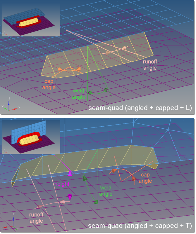
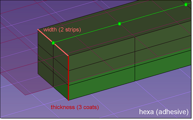
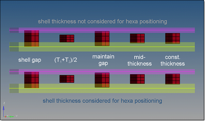
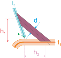
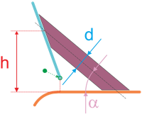
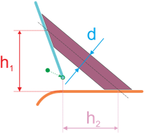
The effects of these options are illustrated in detail in the Seam Panel Realization Methods topic of the HyperMesh User's Guide.

Input

Description

mesh dependent/

mesh Independent

Determines whether the realizations require a node connection.  For a realization which doesn’t need any node connection and the connection is primarily defined via a solver-specific card or the nodes which need to be connected are just defined by a cylinder, then use the mesh independent option. In all other cases the mesh dependent option should be used.

adjust realization / adjust mesh

Determines whether the mesh should be locally adjusted (such as creating transition elements, or remeshing) to ensure proper realization, or if the realization itself should be adjusted--such as allowing non-normal realizations for the sake of locating nodes to create the realization.

This option only displays when mesh independent is active.

quad transition / remesh

The following mesh adjustment options are available to select from this toggle:

quad transition

Creates quads to serve as a transition.

remesh

Remeshes the linked entities to achieve better links.

This toggle only displays when mesh dependent and adjust mesh are active.

imprint / skip imprint

Imprinting is a method of merging two meshes from two different link entities to create a transition mesh that matches up well with both.  See mesh edit - imprint for connectors for more details.

Skip imprint, close-set connectors' transition quads may overlap and interfere with each other, causing one or more realizations to fail.

This toggle only displays when mesh independent, adjust mesh, and quad transition are active.

resolve conflicting imprints

Small conflicts between overlapping transition meshes can be resolved automatically.  Larger conflicts may require a manual imprint, as described in mesh edit - imprint for connectors.

This toggle only displays when mesh independent, adjust mesh, quad transition, and imprint are active.

allow snapping

This check box only displays when mesh independent, adjust mesh, and quad transition are active.


use pitch size to imprint / use avg. mesh size to imprint / size to imprint

Determines the size of the imprint using the pitch size (use pitch size to imprint) or using the average size of the underlying mesh (use avg. mesh size to imprint).

Alternatively, you can specify a specific imprint size by selecting size to imprint.

This switch is only available when mesh dependent, adjust mesh, and quad transition are active.

find nearest nodes / project and find nodes / ensure projection

Determines how the realization will adjust to locate nodes in the linked entities in order to establish links. This decision can be quite involved; see the explanations of each option in detail in the Seam Panel Realization Methods topic of the HyperMesh User's Guide.

This switch is only available when adjust realization is active.


hmtoggle_arrow1Edit Subpanel Inputs

Inputs

Actions

connector

Use this selector to specify the connectors that you wish to edit.

By clicking the edit button the selected connectors will be updated with respect to the new chosen settings. The connectors will become unrealized.

trim

Use trim to reduce the size of a seam connector in order to make it fit better in the model.

1.Using the connector selector, select the seam connector that you would like to trim.
2.To trim the connector at specific points within a specified tolerance, select the snap to connector point check box and enter a tolerance. By default this option is selected, and the tolerance is set to 1.0. If you clear this check box, connector points will be equally distributed when the connector is trimmed.
3.If you selected the snap to connector point check box, toggle the option below it to determine whether to keep or remove the point the connector will be trimmed at.
remove connector point

Removes the point the connector was trimmed at, along with any of its adjacent connector lines.

keep connector point

Trims the connector in a way that both connectors receive a connector point at the trimming position. All of the other connector points will remain at their exact, former positions.

4.To delete the smallest connector piece when the connector is trimmed into two pieces, select the delete smaller connector piece check box.
5.Using the node selector, select the point that you would like to trim the connector at. The connector is immediately trimmed into new, unrealized connectors. The new connectors contain all of the information that was retained from the original connector.
6.Optional: This action can be rejected.

params

spacing / density

See explanation in Inputs for connector creation and link detection above.

end offset / half spacing

See explanation in the Connector Options panel.

group

group / ungroup

Groups or ungroups the selected connectors.

See explanation in Inputs for connector creation and link detection above.


hmtoggle_arrow1Inputs for Seam Partitioning

Inputs

Actions

connector

Use this selector to specify the connectors that you wish to be partitioned.

By clicking the partition button the selected connectors will be updated with respect to the newly chosen settings. The connectors will become unrealized.

non-normal projection

By default this check box is not marked, so during the partition only points with two valid “normal” projections are considered as passed points. This is the recommended setting, especially if the seam connector should be realized as a hexa row afterwards.

tolerance

If this check box is marked, the given tolerance is used for the projection test and the newly created connectors all get this value as tolerance. Otherwise the tolerance already stored on each connector is used for both the projection test and the newly created connectors.

organize connectors with passed projections

Specifies where to organize the newly created "passed" connectors:

default

Creates a new component name CE_partition_passed, and organizes all passed connectors in it.

current component

Organizes the passed connectors into the current component.

original component

Organizes the passed connectors into the same component that the original connectors came from

component

Select an existing component to organize the passed connectors in.

number passed connector IDs

Specifies how the newly created "passed" connectors are numbered:

start with

Specify a certain starting ID that the newly created "passed" connectors should be numbered from. Preexisting IDs are blocked and skipped.

continue

Numbers the newly created "passed" connectors from the highest existing connector ID.

organize connectors with failed projections

Specifies where to organize the newly created "failed" connectors:

default

Creates a component named CE_partition_failed, and organizes all "failed" connectors in it.

current component

Organizes the failed connectors into the current component.

original component

Organizes the failed connectors into the same component where the original connector came from.

component

Select an existing component to organize the failed connectors in.

number failed connectors IDs

Specifies how the newly created "failed" connectors are numbered:

start with

Specify a certain starting ID that the newly created failed connectors should be numbered from. Preexisting IDs are blocked and are skipped.

continue

Numbers all of the newly created failed connectors from the highest existing connector ID.

backup original connectors

Specifies whether the original connectors should be backed up or not.

default

Creates a component named CE_partition_backup, and organizes copies of the original connectors into it, when the backup is activated.

Note:Any other name can be typed in and used as the default. A component with the specified name is created--it does not need to already exist (but see the next option).
component

Select an existing component to organize the backup connectors in.


hmtoggle_arrow1Command Buttons

Button

Action

group/ungroup

When grouping or ungrouping a set of connectors, you must click this command button to apply the grouping or ungrouping.

options

Opens the connector options panel where various settings can be defined

edit

When editing the connector’s spacing, density, or offsets, you must click this command button to apply the changes.

create

Creates the connector(s) with provided input (if sufficient).

partition

Applies the partitioning onto the selected connectors, using the provided input.

reject

Undo the last action.

return

Exits the seam panel.


See Also:

Connector Definition

Connector Realization

HM-3400: Creating Connectors

Connectors Module

An Alphabetical List of HyperMesh Panels