|
»Click here to display Table of Contents«
|

17.1 - Densities |

|

|

|

|
|
17.1 - Densities |
|
|
|

|
|
»Click here to display Table of Contents«
|
17.1 - Densities |
|
|
|
|
|
17.1 - Densities |
|
|
|
|
TitleBox Beam - Densities |
|
||||||||
Number17.1 |
|||||||||
Brief DescriptionA steel box beam, fixed at one end and impacted at the other end by an infinite mass. Results for mesh with different densities are compared. |
|||||||||
Keywords
|
|||||||||
RADIOSS Options
|
|||||||||
Input FileMesh 0: <install_directory>/demos/hwsolvers/radioss/17_BoxBeam/Densities_mesh/mesh0/.../BOXBEAM* Mesh 1: <install_directory>/demos/hwsolvers/radioss/17_BoxBeam/Densities_mesh/mesh1/.../BOXBEAM* Mesh 2: <install_directory>/demos/hwsolvers/radioss/17_BoxBeam/Densities_mesh/mesh2/.../BOXBEAM* Mesh 3: <install_directory>/demos/hwsolvers/radioss/17_BoxBeam/Densities_mesh/mesh3/.../BOXBEAM* |
|||||||||
Technical / Theoretical LevelAdvanced |
|||||||||
Units: mm, ms, g, N, MPa
The material used follows an isotropic elasto-plastic material (/MAT/LAW2) using the Johnson-Cook plasticity model, with the following characteristics:
| • | Initial density: 7.8 x 10⁻³ g/mm3 |
| • | Young modulus: 210000 MPa |
| • | Poisson ratio: 0.3 |
| • | Yield stress: 206 MPa |
| • | Hardening parameter: 450 MPa |
| • | Hardening exponent: 0.5 |
| • | Maximum stress: 340 MPa |
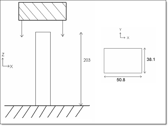
Fig 1: Problem studied.
Four kinds of meshes are used to model the beam. The initial mesh is uniform using a total of 60 x 8 elements. For the three other meshes, the element length is multiplied by 2, 3 and 4, as shown in the following diagram.
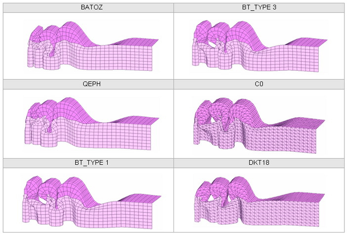
For each model, several element formulations are tested:
| • | BT_TYPE1 |
| • | BT_TYPE3 |
| • | BT_TYPE4 |
| • | QEPH |
| • | BATOZ |
| • | C0 (T3 element) |
| • | DKT18 (T3 element) |
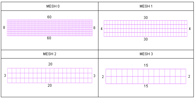
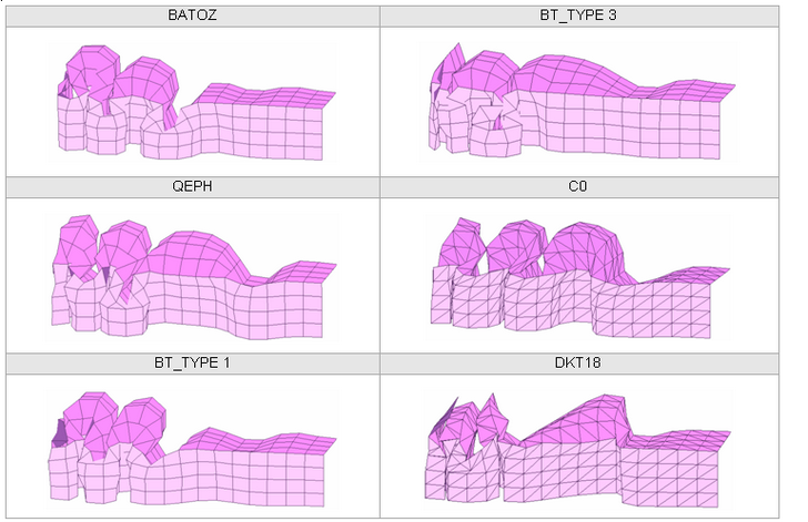
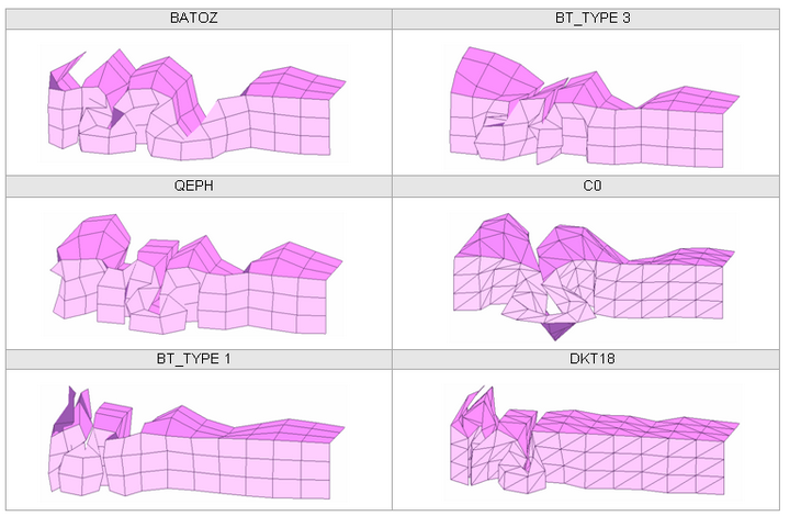
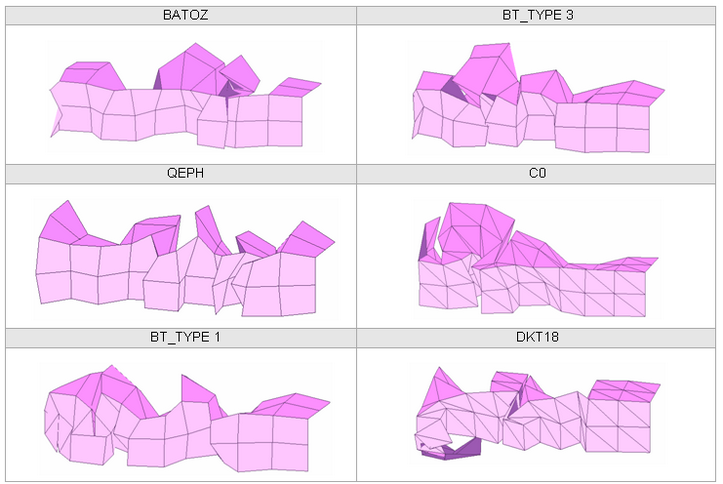
Fig 2: Meshes.
The 3-node shell mesh is obtained by dividing the 4-node shell elements.
| • | Boundary conditions: |
Take into account the symmetry, all nodes in the Y-Z plan are fixed in a Y translation and an X and Z rotation. One quarter of the structure is modeled.
| • | Rigid body: |
The lower (fixed) end is modeled using a rigid body connecting all lower nodes (Z = 0.0). The rigid body is completely fixed using translations and rotations.
| • | Wall: |
The impactor is modeled using a sliding rigid wall having a fixed velocity (13.3 m/s) in a Z direction and is fixed for other translations and rotations.
| • | Interfaces: |
The structure’s self-impact is modeled using a type 7 interface on the full structure. The interface master surface is defined using the complete model. The slave nodes group is defined using the master surface.
On top of the beam, possible edge-to-edge impacts are dealt with using a type 11 self-impacting interface. The edges use the master surface of the type 7 interface as the input surface.
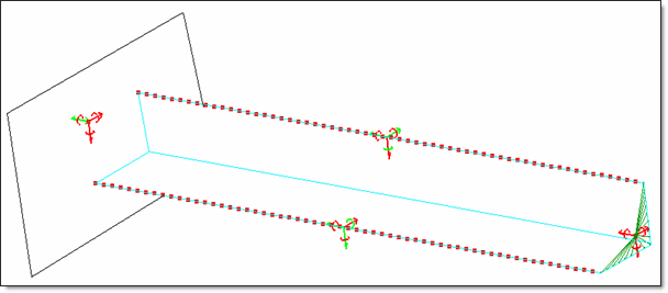
Fig 3: Boundary conditions.
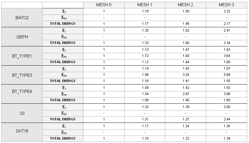
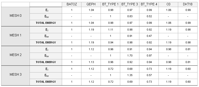
The results are compared using two different views:
| • | The role and influence of the mesh for a given type of element formulation |
| • | The shell element formulations for a given mesh |
Three criteria are used to compare the quality of results obtained:
| • | Crushing force versus displacement |
The crushing force corresponds to normal force in the Z-direction of the impactor (rigid wall), multiplied by 4 due to the symmetry.
In comparison, the displacement corresponds to the Z-direction motion of the rigid wall’s master node.
| • | Hourglass energy |
| • | Total energy |
Total energy is the sum of all energies.
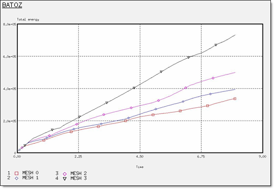
Fig 4: Total energy for a BATOZ formulation.
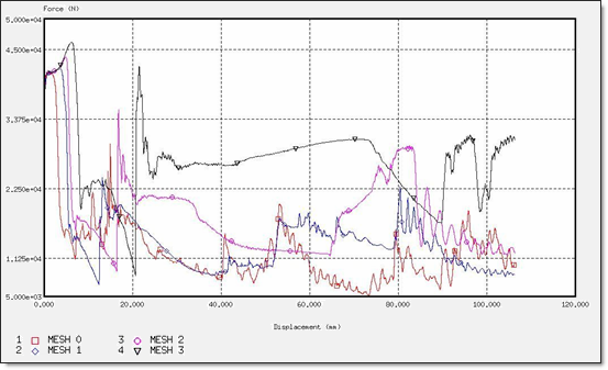
Fig 5: Force for a BATOZ formulation.
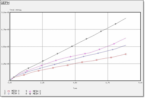
Fig 6: Total energy for a QEPH formulation.
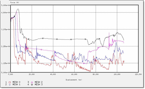
Fig 7: Force for a QEPH formulation.
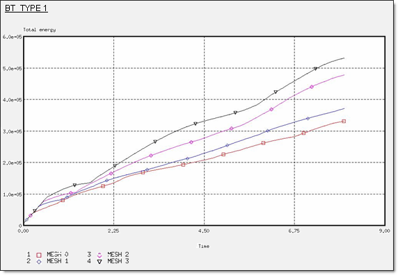
Fig 8: Total energy for a BT_TYPE1 formulation.
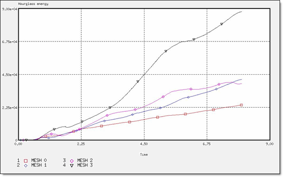
Fig 9: Hourglass energy for a BT_TYPE1 formulation.
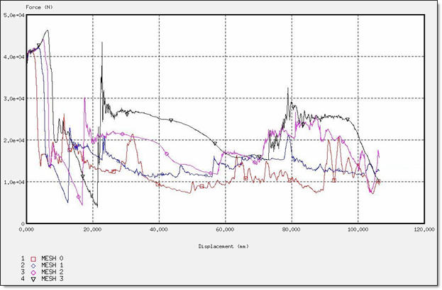
Fig 10: Force for a BT_TYPE1 formulation.
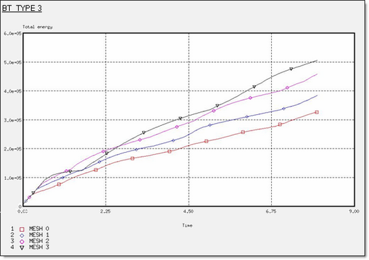
Fig 11: Total energy for a BT_TYPE3 formulation.
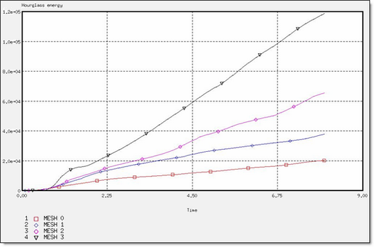
Fig 12: Hourglass energy for a BT_TYPE3 formulation.
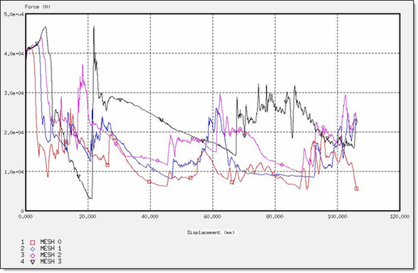
Fig 13: Force for a BT_TYPE3 formulation.
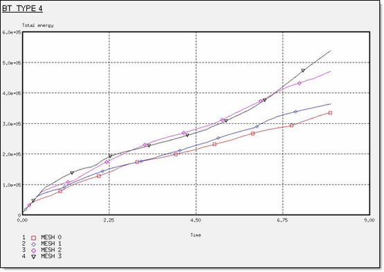
Fig 14: Total energy for a BT_TYPE4 formulation.
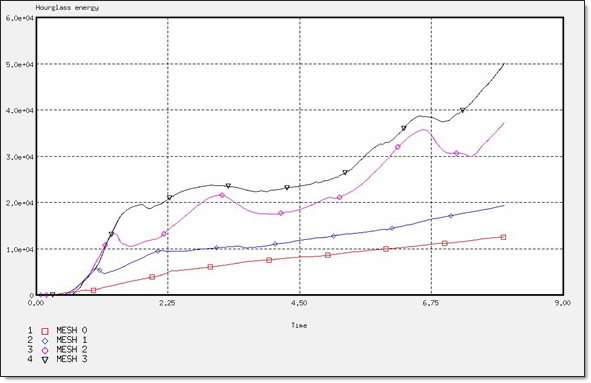
Fig 15: Hourglass energy for a BT_TYPE4 formulation.
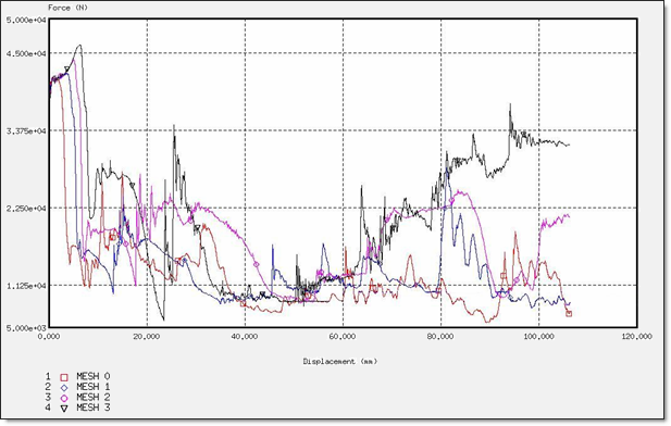
Fig 16: Force for a BT_TYPE4 formulation.
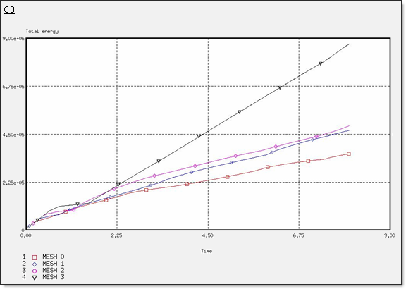
Fig 17: Total energy for a CO formulation.
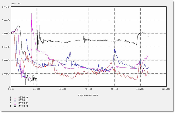
Fig 18: Force for a CO formulation.
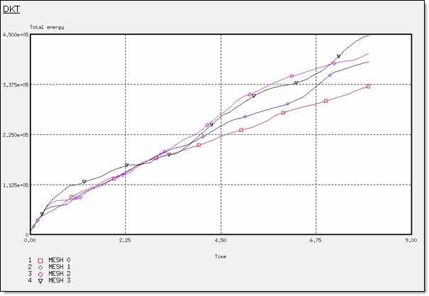
Fig 19: Total energy for a DKT formulation.
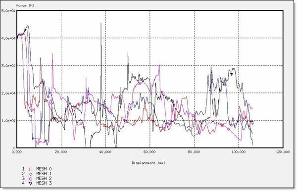
Fig 20: Force for a DKT formulation.
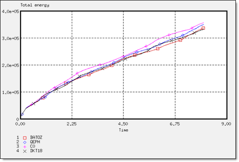
Fig 21: Total energy for different element formulations.
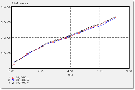
Fig 22: Total energy for different element formulations.
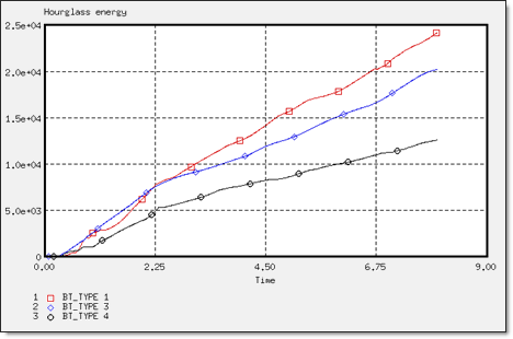
Fig 23: Hourglass energy for different element formulations.
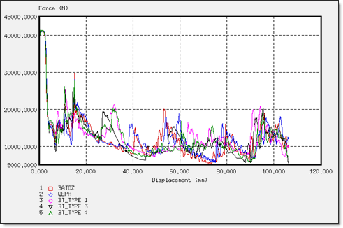
Fig 24: Displacement for different element formulations.
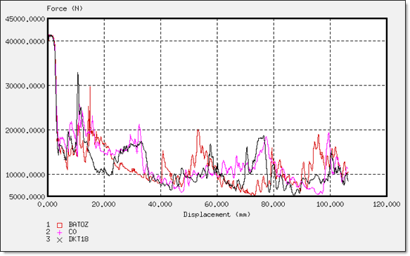
Fig 25: Displacement for different element formulations
|
MESH 0 |
MESH 1 |
MESH 2 |
MESH 3 |
|---|---|---|---|---|
EI t = 8 ms |
3.25 x 10⁵ |
3.82 x 10⁵ |
4.88 x 10⁵ |
7.23 x 10⁵ |
Ehr t = 8 ms |
- |
- |
- |
- |
EK t = 8 ms |
1.32 x 10⁴ |
1.23 x 10⁴ |
1.26 x 10⁴ |
1.10 x 10⁴ |
Total Energy |
3.38 x 10⁵ |
3.94 x 10⁵ |
5.00 x 10⁵ |
7.34 x 10⁵ |
Error t = 8 ms |
0.3% |
1.1% |
1.6% |
2.9% |
Maximum normal force on the wall (N) |
10350 |
10491 |
10953 |
11555 |
|
MESH 0 |
MESH 1 |
MESH 2 |
MESH 3 |
|---|---|---|---|---|
EI t = 8 ms |
3.38 x 10⁵ |
4.55 x 10⁵ |
5.49 x 10⁵ |
8.13 x 10⁵ |
Ehr t = 8 ms |
- |
- |
- |
- |
EK t = 8 ms |
1.32 x 10⁴ |
1.36 x 10⁴ |
1.35 x 10⁴ |
0.93 x 10⁴ |
Total Energy |
3.51 x 10⁵ |
4.68 x 10⁵ |
5.63 x 10⁵ |
8.23 x 10⁵ |
Error t = 8 ms |
2.0% |
2.9% |
3.2% |
8.0% |
Maximum normal force on the wall (N) |
10345 |
10574 |
11335 |
11865 |
|
MESH 0 |
MESH 1 |
MESH 2 |
MESH 3 |
|---|---|---|---|---|
EI t = 8 ms |
3.19 x 10⁵ |
3.60 x 10⁵ |
4.68 x 10⁵ |
5.19 x 10⁵ |
Ehr t = 8 ms |
2.42 x 10⁴ |
4.17 x 10⁴ |
3.87 x 10⁴ |
8.80 x 10⁴ |
EK t = 8 ms |
1.29 x 10⁴ |
1.23 x 10⁴ |
1.16 x 10⁴ |
1.35 x 10⁴ |
Total Energy |
3.32 x 10⁵ |
3.72 x 10⁵ |
4.79 x 10⁵ |
5.32 x 10⁵ |
Error t = 8 ms |
-6.4% |
-9.3% |
-5.8% |
-11.5% |
Maximum normal force on the wall (N) |
10344 |
10505 |
10971 |
11569 |
|
MESH 0 |
MESH 1 |
MESH 2 |
MESH 3 |
|---|---|---|---|---|
EI t = 8 ms |
3.14 x 10⁵ |
3.73 x 10⁵ |
4.46 x 10⁵ |
4.94 x 10⁵ |
Ehr t = 8 ms |
2.02 x 10⁴ |
3.80 x 10⁴ |
6.56 x 10⁴ |
11.90 x 10⁴ |
EK t = 8 ms |
1.31 x 10⁴ |
1.24 x 10⁴ |
1.32 x 10⁴ |
1.29 x 10⁴ |
Total Energy |
3.27 x 10⁵ |
3.85 x 10⁵ |
4.60 x 10⁵ |
5.07 x 10⁵ |
Error t = 8 ms |
-5.5% |
-8.2% |
-11.0% |
-16.7% |
Maximum normal force on the wall (N) |
10353 |
10526 |
11000 |
11670 |
|
MESH 0 |
MESH 1 |
MESH 2 |
MESH 3 |
|---|---|---|---|---|
EI t = 8 ms |
3.23 x 10⁵ |
3.52 x 10⁵ |
4.60 x 10⁵ |
5.26 x 10⁵ |
Ehr t = 8 ms |
1.26 x 10⁴ |
1.94 x 10⁴ |
3.74 x 10⁴ |
5.02 x 10⁴ |
EK t = 8 ms |
1.30 x 10⁴ |
1.24 x 10⁴ |
1.21 x 10⁴ |
1.31 x 10⁴ |
Total Energy |
3.36 x 10⁵ |
3.64 x 10⁵ |
4.72 x 10⁵ |
5.39 x 10⁵ |
Error t = 8 ms |
-3.3% |
-4.0% |
-5.8% |
-6.5% |
Maximum normal force on the wall (N) |
10344 |
10538 |
11011 |
11568 |
|
MESH 0 |
MESH 1 |
MESH 2 |
MESH 3 |
|---|---|---|---|---|
EI t = 8 ms |
3.45 x 10⁵ |
4.56 x 10⁵ |
4.79 x 10⁵ |
8.64 x 10⁵ |
Ehr t = 8 ms |
- |
- |
- |
- |
EK t = 8 ms |
1.29 x 10⁴ |
1.30 x 10⁴ |
1.10 x 10⁴ |
1.12 x 10⁴ |
Total Energy |
3.58 x 10⁵ |
4.69 x 10⁵ |
4.90 x 10⁵ |
8.75 x 10⁵ |
Error t = 8 ms |
0.2% |
0.8% |
1.7% |
2.5% |
Maximum normal force on the wall (N) |
10355 |
10344 |
10875 |
11435 |
MESH 0 |
MESH 1 |
MESH 2 |
MESH 3 |
|
|---|---|---|---|---|
EI t = 8 ms |
3.21 x 10⁵ |
3.75 x 10⁵ |
3.97 x 10⁵ |
4.32 x 10⁵ |
Ehr t = 8 ms |
- |
- |
- |
- |
EK t = 8 ms |
1.29 x 10⁴ |
1.34 x 10⁴ |
1.13 x 10⁴ |
1.45 x 10⁴ |
Total Energy |
3.34 x 10⁵ |
3.88 x 10⁵ |
4.08 x 10⁵ |
4.47 x 10⁵ |
Error t = 8 ms |
0.5% |
0.8% |
1.6% |
1.9% |
Maximum normal force on the wall (N) |
10348 |
10367 |
10800 |
11139 |