|
»Click here to display Table of Contents«
|

CBAR |

|

|

|

|
|
CBAR |
|
|

|

|
|
»Click here to display Table of Contents«
|
CBAR |
|
|
|
|
|
CBAR |
|
|
|
|
Bulk Data Entry
CBAR – Simple Beam Element Connection
Description
The CBAR bulk data entry defines a simple beam element (BAR) of the structural model.
Format
(1) |
(2) |
(3) |
(4) |
(5) |
(6) |
(7) |
(8) |
(9) |
(10) |
CBAR |
EID |
PID |
GA |
GB |
X1/G0 |
X2 |
X3 |
OFFT |
|
|
PA |
PB |
W1A |
W2A |
W3A |
W1B |
W2B |
W3B |
|
|
Field |
Contents |
EID |
Unique element identification number. No default (Integer > 0) |
PID |
PBAR or PBARL property entry identification number. Default = EID (Integer > 0) |
GA,GB |
Grid point identification numbers of connection points. No default (Integer > 0 or <PartName.number>; GA ≠ GB) See comment 6. |
X1,X2,X3 |
Components of vector v, at end A, measured at end A, parallel to the components of the displacement coordinate system for GA, or the basic coordinate system, to determine (with the vector from end A to end B) the orientation of the element coordinate system for the BAR element (Comment 4). No default (Real) |
G0 |
Grid point identification number to optionally supply X1, X2, X3. Direction of orientation vector is GA to G0. No default (Integer > 0 or <PartName.number>) See comment 6. |
OFFT |
Character string specifying the interpretation of the offset vector specification (Comment 5). Default = GGG (Character or blank) |
PA, PB |
Pin flags for bar ends A and B, respectively. Used to remove connections between the grid point and selected degrees-of-freedom of the bar. The degrees-of-freedom are defined in the element’s coordinate system. The bar must have stiffness associated with the PA and PB degrees-of-freedom to be released by the pin flags. For example, if PA=4 is specified, the PBAR entry must have a value for J, the torsion stiffness. No default (Integer > 0; up to 5 of the unique digits 1-6 with no embedded blanks) |
W1A,W2A,W3A |
Components of offset vectors wa and wb in displacement coordinate systems at points GA and GB, respectively, or in the element coordinate system (Comment 4). Default = blank (Real or blank) |
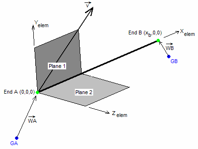
Fig 1: Bar element coordinate system (for CBAR element)
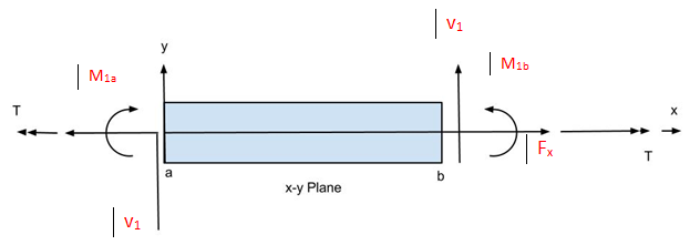
Fig 2: Moments and Internal Forces in the x-y Plane (for a CBAR element)
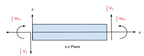
Fig 3: Moments and Internal Forces in the x-z Plane (for a CBAR element)
| 1. | If there are no pin flags or offsets, the continuation may be omitted. |
| 2. | G0 cannot be located at GA or GB. |
| 3. | If X1/G0 is a positive integer and X2 and X3 are blank, then G0 is used to orient the element, otherwise X1, X2, X3 is used. |
| 4. | The OFFT character string specifies how the offset and orientation vector components are computed. By default, the offset vectors are specified in the Global (local displacement) coordinate system of each grid A and B, and the orientation vector is specified in the Global coordinate system of grid A. Using the codes below, the offset vector can be specified in the element coordinate system and the orientation vector can be specified in the basic coordinate system. The valid character strings and their meanings are shown below: |
OFFT |
Orientation Vector |
End A Offset |
End B Offset |
|---|---|---|---|
GGG |
Global |
Global |
Global |
BGG |
Basic |
Global |
Global |
GGO |
Global |
Global |
Element |
BGO |
Basic |
Global |
Element |
GOG |
Global |
Element |
Global |
BOG |
Basic |
Element |
Global |
GOO |
Global |
Element |
Element |
BOO |
Basic |
Element |
Element |
The element system x-axis is defined from GA to GB. The orientation vector and the element system x-axis are then used to define the z and y axes of the element system. A vector is formed from the cross product of a vector going from Grid A to Grid B and the orientation vector to create the element coordinate z-direction.
| 5. | Offset vectors are treated like rigid elements. The length of the offset vectors is not affected by thermal loads. |
| 6. | Supported local entries in specific parts can be referenced by the use of “fully qualified references” on CBAR entries in the model. A fully qualified reference (“PartName.number”) is similar to the format of a numeric reference. “PartName” is the name of the part that contains the referenced local entry (part names are defined on the BEGIN Bulk Data Entry in the model). “number” is the identification number of a referenced local entry in the part “PartName”. Refer to Parts and Instances in the User’s Guide for detailed information on the use of fully qualified references. |
| 7. | This card is represented as a bar2 element in HyperMesh. |
See Also: