|
»Click here to display Table of Contents«
|

CORD2C |

|

|

|

|
|
CORD2C |
|
|

|

|
|
»Click here to display Table of Contents«
|
CORD2C |
|
|
|
|
|
CORD2C |
|
|
|
|
Bulk Data Entry
CORD2C – Cylindrical Coordinate System Definition, Form 2
Description
This entry defines a cylindrical coordinate system using three grid points specified with respect to a reference coordinate system. The coordinates of the three non-collinear grid points are used to uniquely define the coordinate system. The first point defines the origin. The second point defines the direction of the Z-axis. The third lies in the X-Z plane (see Figure 1).
Format
(1) |
(2) |
(3) |
(4) |
(5) |
(6) |
(7) |
(8) |
(9) |
(10) |
CORD2C |
CID |
RID |
A1 |
A2 |
A3 |
B1 |
B2 |
B3 |
|
|
C1 |
C2 |
C3 |
|
|
|
|
|
|
|
Field |
Contents |
CID |
Unique coordinate system identification number. (Integer > 0) |
RID |
Identification number of a reference coordinate system that is defined independently from this coordinate system (see comment 7). Default = 0 (Integer > 0) |
A1,A2,A3 |
Coordinates of three points in the reference coordinate system (RID). If RID is blank or 0, the reference coordinate system is the default basic coordinate system. (Real) |
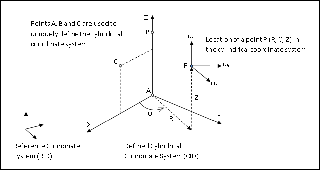
Figure 1: Defining a Cylindrical Coordinate System (CID) using points A, B and C with reference to another coordinate system (RID).
| 1. | The three points (A1, A2, A3), (B1, B2, B3), (C1, C2, C3) must be unique and non-collinear. Non-collinearity is checked by the geometry processor. |
| 2. | Coordinate system identification numbers (CID) on all CORD1C, CORD1R, CORD1S, CORD2C, CORD2R, CORD2S, CORD3R, and CORD4R entries must be unique. |
| 3. | A duplicate identification number is allowed if the CID and GID are identical and the coordinates are within the value set by PARAM, DUPTOL (see Guidelines for Bulk Data Entries for further information). |
| 4. | The location of a grid point (P in Figure 1) in this cylindrical coordinate system is given by (R, θ, and Z). Where, θ is measured in degrees. |
| 5. | The displacement coordinate directions at P are dependent on the location of P (Ur, Uθ, and Uz) as shown in Figure 1. The displacements in these three directions at the grid point are specified in units of length. |
In OptiStruct, the cylindrical and spherical coordinate systems are internally resolved to entity-position-dependent (example: GRID) rectangular systems. Therefore, when a grid point is located in a cylindrical system, OptiStruct constructs a rectangular system at that location for the grid point. The R-direction corresponds to the X-axis, the Z-axis is the same, and the θ axis is tangential to the X (or R) axis. Now the various degrees-of-freedom can be resolved (vis-à-vis constraints) similar to a general rectangular system. Care must be taken to observe that the internally generated rectangular systems are dependent on the grid point location in the cylindrical system. So they may be different for different grid point locations within the same cylindrical system.
| 6. | Points on the Z-axis should not have their displacement directions defined in this coordinate system due to ambiguity. |
| 7. | The reference coordinate system (RID) should be independently defined or left blank. If blank (or 0), the reference coordinate system is the default basic coordinate system. In such cases, A, B and C are defined with respect to the basic coordinate system. |
| 8. | This card is represented as a system in HyperMesh. |
See Also: