|
»Click here to display Table of Contents«
|

CORD2R |

|

|

|

|
|
CORD2R |
|
|

|

|
|
»Click here to display Table of Contents«
|
CORD2R |
|
|
|
|
|
CORD2R |
|
|
|
|
Bulk Data Entry
CORD2R – Rectangular Coordinate System Definition, Form 2
Description
The entry defines a rectangular coordinate system by using three grid points. The coordinates of the three non-collinear grid points are used to uniquely define the coordinate system. The first point defines the origin. The second defines the direction of the Z-axis. The third point defines a vector, which, with the Z-axis, defines the X-Z plane (see Figure 1).
(1) |
(2) |
(3) |
(4) |
(5) |
(6) |
(7) |
(8) |
(9) |
(10) |
CORD2R |
CID |
RID |
A1 |
A2 |
A3 |
B1 |
B2 |
B3 |
|
|
C1 |
C2 |
C3 |
|
|
|
|
|
|
|
Field |
Contents |
CID |
Unique coordinate system identification number. (Integer > 0) |
RID |
Identification number of a coordinate system that is defined independently from this coordinate system (see comment 6). Default = 0 (Integer > 0) |
A1,A2,A3 |
Coordinates of three points in the reference coordinate system (RID). If RID is blank or 0, the reference coordinate system is the default basic coordinate system. (Real) |
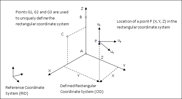
Figure 1: Defining a Rectangular Coordinate System (CID) using points A, B and C with reference to another coordinate system (RID).
| 1. | The three points (A1, A2, and A3), (B1, B2, and B3), and (C1, C2, and C3) must be unique and non-collinear. Non-collinearity is checked by the geometry processor. |
| 2. | Coordinate system identification numbers on all CORD1R, CORD1C, CORD1S, CORD2R, CORD2C, CORD2S, CORD3R, and CORD4R entries must all be unique. |
| 3. | A duplicate identification number is allowed if the CID and GID are identical and the coordinates are within the value set by PARAM, DUPTOL (see Guidelines for Bulk Data Entries for further information). |
| 4. | The location of a grid point (P in Figure 1) in this rectangular coordinate system is given by (X, Y, and Z). |
| 5. | The displacement coordinate directions at P are (Ux, Uv, and Uz) as shown in Figure 1. |
| 6. | The reference coordinate system (RID) should be independently defined or left blank. If blank (or 0), the reference coordinate system is the default basic coordinate system. In such cases, A, B and C are defined with respect to the basic coordinate system. |
| 7. | This card is represented as a system in HyperMesh. |
See Also: