|
»Click here to display Table of Contents«
|

CWELD |

|

|

|

|
|
CWELD |
|
|

|

|
|
»Click here to display Table of Contents«
|
CWELD |
|
|
|
|
|
CWELD |
|
|
|
|
Bulk Data Entry
CWELD – Weld or Fastener Element Connection
Description
Defines a weld or fastener connecting two surface patches or points.
Format
(1) |
(2) |
(3) |
(4) |
(5) |
(6) |
(7) |
(8) |
(9) |
(10) |
CWELD |
EWID |
PWID |
GS |
TYP |
GA |
GB |
SPTYP |
|
|
|
GA1/SHIDA |
GA2/SHIDB |
GA3 |
GA4 |
GA5 |
GA6 |
GA7 |
GA8 |
|
|
GB1 |
GB2 |
GB3 |
GB4 |
GB5 |
GB6 |
GB7 |
GB8 |
|
|
|
|
Alternate Formats of CWELD Card – PARTPAT/ELPAT
The alternative formats of CWELD listed below are useful in cases when the weld diameter extends beyond a single shell element. These options connect up to 3x3 shell elements per patch (possibly more for triangular elements) on each side of weld element.
Format (Alternate)
(1) |
(2) |
(3) |
(4) |
(5) |
(6) |
(7) |
(8) |
(9) |
(10) |
CWELD |
EWID |
PWID |
GS |
PATCHTYP |
GA |
GB |
|
|
|
|
PIDA/SHIDA |
PIDB/SHIDB |
|
|
|
|
|
|
|
|
XS |
YS |
ZS |
|
|
|
|
|
|
|
|
Field |
Contents |
EWID |
Unique element identification number. No default (Integer > 0) |
PWID |
A PWELD entry identification number. Default = EWID (Integer > 0) |
GS |
Identification number of a grid point which defines the location of the connector. Required when TYP is GRIDID or ELEMID and GA and GB are unspecified (Comments 2 and 4). No default (Integer > 0 or <PartName.number>) See comment 14. |
TYP |
Character string indicating how the connection is defined. GRIDID indicates that the connection is defined with grid identification numbers GA# and GB#, respectively (Comment 3). ELEMID indicates that the connection is defined with shell element identification numbers SHIDA and SHIDB (Comment 7). ALIGN indicates that the connection is defined between two shell vertex grid points (Comment 8). No default (GRIDID, ELEMID or ALIGN) |
GA, GB |
When TYP is GRIDID or ELEMID, these represent grid identification numbers of piercing points on surface A and surface B, respectively (Comment 4). When TYPE is ALIGN, these represent vertex grid identification numbers of the first and second shells, respectively. No default (Integer > 0 or <PartName.number>) See comment 14. |
SPTYP |
String indicating types of surface patches A and B. Q indicates quadrilateral surface patch, and T indicates triangular surface patch. Required when TYP is GRIDID (Comment 5). No default (QQ, TT, QT, TQ, Q or T) |
GA# |
Grid identification numbers of the first surface patch. GA1 to GA3 are required (Comment 6). No default (Integer > 0 or <PartName.number>) See comment 14. |
GB# |
Grid identification numbers of the second surface patch (Comment 6). Default = blank (Integer > 0 or <PartName.number>) See comment 14. |
PATCHTYP |
The type of connection between the patches. Either format connects up to 3x3 elements per patch (possibly more for triangular elements). See comment 12. For PARTPAT, the connection of surface patch to surface patch is defined by specifying the property numbers of shells on side A and B, PIDA and PIDB, respectively. For ELPAT, the connection of surface patch to surface patch is defined by specifying IDs of shells SHIDA and SHIDB, respectively. |
PIDA,PIDB |
Property identification numbers of PSHELL entries defining surface A and B, respectively. Required for PARTPAT. Integer > 0, PIDA ≠ PIDB. |
SHIDA, SHIDB |
Element identification numbers of shells defining weld ends A and B, respectively. Required for ELPAT. Integer > 0, SHIDA ≠ SHIDB |
XS, YS, ZS |
Coordinates of point that defines the location of the weld in the basic coordinate system. It is an alternate way of specifying the location of GS. Available with PARTPAT/ELPAT options only. Real |
| 1. | CWELD defines a flexible connection between two surface patches, between a point and a surface patch, or between two shell vertex grid points. See figure below: |
Connection between two surface patches
Connection between a point and a surface patch
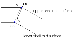
Connection between two shell vertex grid points
| 2. | GS is ignored, if TYP is ALIGN. |
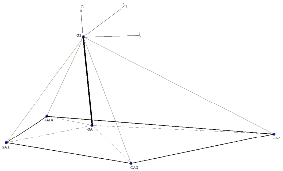
| 3. | If TYP is GRIDID, either a point to patch (GS to GA#) or a patch to patch (GA# to GB#) connection is defined. For the patch to patch connection, GA# describes the first surface patch and GB# describes the second surface patch. |
| 4. | The input of the piercing points GA and GB is optional when TYP is GRIDID and ELEMID. If GA or GB are not specified, they are generated from the normal projection of GS onto the surface patches. If GA and/or GB are specified, they take precedence over GS in defining the respective end points. Also, their locations will be corrected so that they lie on surface patch A and B, respectively. If GS is not specified, both GA and GB are required. The length of the connector is the distance from GA to GB. |
| 5. | SPTYP defines the type of surface patches to be connected. SPTYP is required when TYP is GRIDID to identify quadrilateral or triangular patches. Valid combinations are: |
SPTYP |
Description |
|---|---|
Connects a quadrilateral surface patch A (QUAD4 or QUAD8) with a quadrilateral surface patch B (QUAD4 or QUAD8). |
|
QT |
Connects a quadrilateral surface patch A (QUAD4 or QUAD8) with a triangular surface patch B (TRIA3 or TRIA6). |
TT |
Connects a triangular surface patch A (TRIA3 or TRIA6) with a triangular surface patch B (TRIA3 or TRIA6). |
TQ |
Connects a triangular surface patch A (TRIA3 or TRIA6) with a quadrilateral surface patch B (QUAD4 or QUAD8). |
Q |
Connects a grid point GB (or GS if GB not provided) with a quadrilateral surface patch A (QUAD4 or QUAD8). Surface patch B should not be specified. |
T |
Connects a grid point GB (or GS if GB not provided) with a triangular surface patch A (TRIA3 or TRIA6). Surface patch B should not be specified. |
| 6. | GA# are required when TYP is GRIDID. At least 3, and at most 8, grid IDs may be specified for GA#. Triangular and quadrilateral element definition sequences apply for the order of GA# and GB#, see below. Missing mid-side nodes are allowed. |
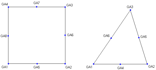
Quadrilateral and Triangular Surface Patches as defined when TYP is GRIDID
| 7. | When TYP is ELEMID, a point to patch connection is defined, GS to SHIDA or a patch to patch connection, SHIDA to SHIDB. SHIDA and SHIDB must be valid shell element identification numbers. |
| 8. | When TYP is ALIGN, a point to point connection is defined. GA and GB are required. GA and GB are not required when TYP is GRIDID or ELEMID. |
| 9. | Forces and moments are output in the element coordinate system (shown in comment 10 below). |
The element x-axis points from GA to GB. The element y-axis lies on the plane created by the element x-axis and the smallest component of the element x-axis is the basic coordinate system, and is orthogonal to the element x-axis. The element z-axis is the cross-product of the element x-axis and the element y-axis.
| 10. | The output format of the forces and moments, including the sign convention, is identical to the CBAR element. |
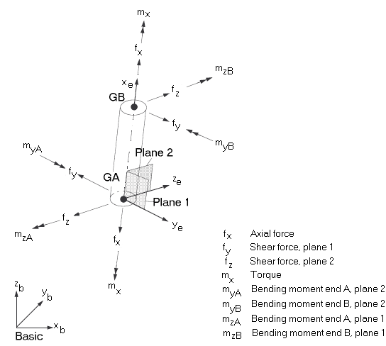
Element coordinate system and sign convention of element forces
| 11. | Diagnostic printouts, checkout runs and non-default setting of search and projection parameters are requested on the SWLDPRM bulk data entry. It is recommended to start with default settings. |
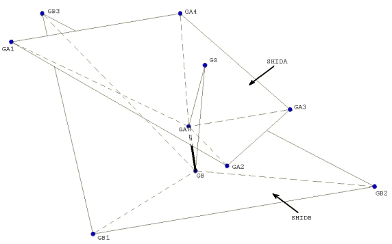
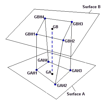
| 12. | The formats PARTPAT and ELPAT connect shell element patches on side A and B. The patches are identified by specifying SHIDA and SHIDB (for ELPAT connection) and by specifying property IDs PIDA and PIDB for PARTPAT connection (wherein SHIDA and SHIDB are found by appropriate search of best projections of GS (or GA) onto the surfaces A and B, respectively). The piercing points GA and GB are found by appropriate projections onto SHIDA and SHIDB. Then the axis GA-GB is used to define four pairs of auxiliary points GAHi, GBHi, i=1,4 that are located on patches A and B, respectively. The cross-section area of the resulting hexahedral is equivalent to the area of the weld. The weld stiffness matrix is first built using the auxiliary points and then constrained to supporting shell nodes using respective shape functions. |
| 13. | Fastener elements are ignored in heat transfer analysis. |
| 14. | Supported local entries in specific parts can be referenced by the use of “fully qualified references” on CBAR entries in the model. A fully qualified reference (“PartName.number”) is similar to the format of a numeric reference. “PartName” is the name of the part that contains the referenced local entry (part names are defined on the BEGIN Bulk Data Entry in the model). “number” is the identification number of a referenced local entry in the part “PartName”. Refer to Parts and Instances in the User’s Guide for detailed information on the use of fully qualified references. |
| 15. | This card is represented as a rod element in HyperMesh. |
See Also: