|
»Click here to display Table of Contents«
|

PWELD |

|

|

|

|
|
PWELD |
|
|

|

|
|
»Click here to display Table of Contents«
|
PWELD |
|
|
|
|
|
PWELD |
|
|
|
|
Bulk Data Entry
PWELD – WELD Element Property
Description
Defines properties of connector (CWELD) elements.
Format
(1) |
(2) |
(3) |
(4) |
(5) |
(6) |
(7) |
(8) |
(9) |
(10) |
PWELD |
PID |
MID |
D |
|
|
MSET |
|
TYPE |
|
|
DTAB |
TID |
|
|
|
|
|
|
|
|
Field |
Contents |
PID |
Property identification number. No default (Integer > 0) |
MID |
Material identification number. See comment 1. No default (Integer > 0) |
D |
Diameter of the connector. See comment 1. No default (Real > 0.0) |
MSET |
Flag to eliminate m-set degrees-of-freedom. = ON: generates explicit m-set constraints. = OFF (default): incorporates constraints at the element stiffness matrix level avoiding explicit m-set constraint equations. The exact same results will be obtained regardless of this choice. Default = OFF (ON or OFF) |
TYPE |
Connection type. See comment 2. SPOT: indicates spot weld connector. Set to activate Spot Weld Fatigue Analysis. blank: indicates general connector. Default = blank (SPOT or blank) |
DTAB |
The weld element diameter is determined from the table TID. |
TID |
Identification number of a TABLEDi entry that defines the weld element diameter as a function of the minimum shell thickness of the corresponding shell elements (sheets). See comment 3 No default (Integer > 0) |
Comments
| 1. | Material MID, diameter D, and the length are used to calculate the stiffness of the connector in 6 directions. MID can only refer to the MAT1 bulk data entry. The length is the distance of GA to GB (see below). |
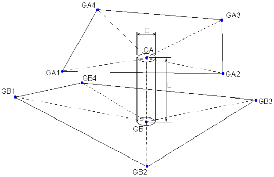
Length and Diameter of Weld connector
| 2. | If TYPE=SPOT and if the formats PARTPAT, ELPAT, or ELEMID on the CWELD entry are used, then the effective length for the stiffness of the CWELD element is set to |
| 3. | The TID field references a TABLEDi entry that defines the weld diameter as a function of minimum attached shell thicknesses. |
| • | TID consists of list of minimum thickness values (X) vs corresponding weld diameters (Y). |
| • | From the table TID lookup you get Y (weld diameter) for the min thickness (used for the lookup). |
| 4. | This card is represented as a property in HyperMesh. |
See Also: