Summary
The aim of this example is to introduce high quality time step control Advanced Mass Scaling (AMS). Time step will be computed by RADIOSS. Small element sizes may lead to small time step and; therefore, occupy many CPU sources. Increase time step could use time step control, but using old option of time step control will for example increase the mass or kinematic energy. If the increase is not small enough, it will affect the solution, but with this high quality time step control AMS, there is no change in inertia effects on translational global acceleration, non-diagonal mass added. With AMS similar results are received, like the old one, but with much less computation time.
Title
Blow Molding with AMS
|
|
Number
44.1
|
Brief Description
Blow molding with Advanced Mass Scaling (AMS).
|
Keywords
| • | Advanced Mass Scaling (/AMS) |
| • | Visco Elastic Plastic Piecewise Linear Material law (/MAT/LAW66) |
| • | Rayleigh damping (/DAMP) |
|
RADIOSS Options
| • | Boundary condition (/BCS) |
|
Input File
Example44: <install_directory>/demos/hwsolvers/radioss/44_blow_molding_ams/E4_66_AMS/*
<install_directory>/demos/hwsolvers/radioss/44_blow_molding_ams/E4_66_no_dt_control/*
<install_directory>/demos/hwsolvers/radioss/44_blow_molding_ams/E4_66_Noda_CST/*
|
Technical / Theoretical Level
Advanced
|
Overview
Description of the Physical Problem
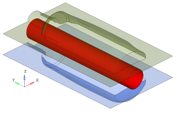
A hollow plastic parison (tube-like) has been formed. Then the parison is clamped into a mold and air is pumped into it. Here pressure load is used to model air pressure. Let it push the plastic out and then match the mold. The dimension of the parison is cylinder with 30mm and its thickness 2mm. The dimension of the mold is 207mm x 120mm and its thickness is 1.0 mm.
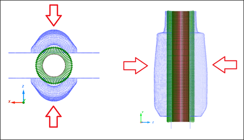
Fig 1: Problem description for blow molding
Units: mm, s, Mg , N , MPa
The mold material using the Elastic model (/MAT/ELAST), with the following characteristics:
| • | Initial density = 7.8e-9 Mg/mm3 |
| • | Young modulus = 200000 MPa |
The plastic parison using Visco Elastic Plastic Piecewise Linear material (/MAT/LAW66), with the following characteristics:
| • | Initial density = 1e-9 Mg/mm3 |
Analysis, Assumptions and Modeling Description
Modeling Methodology of Blow Model with AMS
Blow molding using AMS will be modeled as follows:
| 1. | Define /AMS in Starter. Select the part group which will use AMS. If the part group has not been specified, then the whole model will use AMS. |
| 2. | Use /DT/AMS in Engine. For example: |
/DT/AMS
0.67 1.15e-4
RADIOSS Options Used
Rigid body and Boundary conditions:
| • | Using rigid body, two molds have been fixed in all direction of rotation and translations of y-direction and x-direction. They are only free in z-direction (translation). |
Pressure Load:
| • | The air pressure on the plastic parison is modeled using pressure load /PLOAD from inside towards outside |
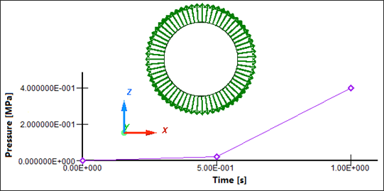
Fig. 2: Pressure load on plastic parison
Imposed displacement:
| • | Two molds are moved in opposite directions with imposed displacement. |
Interface:
| • | Type 7 interface has been defined between mold and plastic parison with friction 0.7. |
Simulation Results and Conclusions
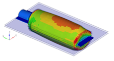
The following figures show the plastic strain, von Mises stress on plastic parison. (See below).
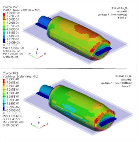
Fig. 3: Plastic strain and von Mises stress on plastic parison
Performance
Using the AMS technique, CPU time is reduced by a factor of approximately 3, in this case.
Below shows results comparison of tests:
| • | Without time step control (no mass scaling) |
| • | With standard mass scaling /DT/NODE/CST |
Table 1: Results of model computation with and without AMS
|
Without time step control
|
With standard mass scaling /DT/NODA/CST
|
With AMS
|
Time step(s)
|
1.15e-4
|
0.34e-04
|
1.15e-4
|
Total Number of cycle
|
78200
|
24280
|
6966
|
CPU time(s)
|
2027.82
|
723.02
|
522.83
|
Speed-up
|
-
|
2.80
|
3.88
|
Results quality
|
-
|
Bad
|
Good
|
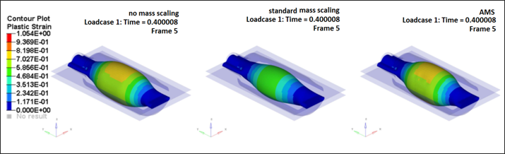
Fig. 4: Plastic strain for tests without time step control (no mass scaling). With /DT/NODA/CST and with AMS at time 0.4s.
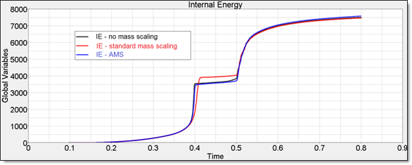
Fig. 5: Internal energy on plastic parison with and without AMS
It shows at time 0.4s for the same speed up factor with AMS you get more accurate results compare with no mass scaling test than with node mass scaling.
Conclusion
To obtain a CPU saving factor of about 3, the target time step should be about 10 times higher than the one without AMS; AMS treatment itself is taking some CPU cost.
Standard mass scaling technique can also speed up the calculation by a factor of about 3, but the results quality will be affected.
In general, AMS technique for a given speed up, gives more accurate results than standard mass scaling.
The AMS technique does not change the total mass; the mass is added only on non-diagonal terms of the mass matrix.
It is applicable to the entire model.
There is no change in inertia effects on translational global acceleration
Note:
| • | Result accuracy, in terms of stress and strains, is normally not affected; by the way AMS is affecting Eigen modes of the structure(s) to which it is applied. Higher frequencies are lowered. |
| • | AMS technique is highly scalable; large models could show even more significant speed up factors. |


