Frequency Response Analysis |

|

|

|

|
|
Frequency Response Analysis |

|

|

|

|
Frequency response analysis is used to calculate the response of a structure to steady state oscillatory excitation. Typical applications are noise, vibration and harshness (NVH) analysis of vehicles, rotating machinery, transmissions, and powertrain systems.
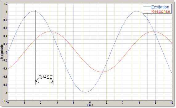
Frequency response analysis is used to compute the response of the structure, which is actually transient, in a static frequency domain. The loading is sinusoidal. A simple case is a load of given amplitude at a specified frequency. The response occurs at the same frequency, and damping would lead to a phase shift (Figure 1).
The loads can be forces, displacements, velocity, and acceleration. They are dependent on the excitation frequency ![]() .
.
The results from a frequency response analysis are displacements, velocities, accelerations, forces, stresses, and strains. The responses are usually complex numbers that are either given as magnitude and phase angle or as real and imaginary part.
OptiStruct supports Direct and Modal frequency response analysis.

Figure 1: Excitation and response of a frequency response analysis.
Direct frequency response analysis can be used to compute the structural responses directly at discrete excitation frequencies ![]() by solving a set of complex matrix equations. The basic equation of motion set to be solved is shown below:
by solving a set of complex matrix equations. The basic equation of motion set to be solved is shown below:
![]()
Where,
M is the mass matrix
C is the damping matrix
K is the stiffness matrix
u is the displacement vector
f is the load vector
![]() is the angular frequency at which loading is applied. The applied harmonic excitation can be assumed to generate a harmonic response. The displacement vector can be written as shown below:
is the angular frequency at which loading is applied. The applied harmonic excitation can be assumed to generate a harmonic response. The displacement vector can be written as shown below:
![]()
Substituting the assumed harmonic displacement response into the first equation and rewriting the damping matrix C.
![]()
There are several ways to define damping in the system.
| 1. | Using a uniform structural damping coefficient G. |
| 2. | Structural element damping is defined using the damping coefficient, GE on the material entries, as well as GE on bushing and spring element property definitions. These form the matrix CGE. |
| 3. | Viscous damping is generated by damper elements. These form the matrix C1. |
The equation of motion is solved directly using complex algebra.
The frequency response loads and boundary conditions are defined in the bulk data section of the input deck. They need to be referenced in the subcase information section using an SPC and DLOAD statement in a SUBCASE.
OptiStruct does not support inertia relief for direct frequency response analysis. The solver will error out if it is attempted.
A frequency set must be referenced using a FREQUENCY statement.
In addition to the various damping elements and material damping, uniform structural damping G can be applied using PARAM, G.
The modal method first performs a normal modes analysis to obtain the eigenvalues ![]() and the corresponding eigenvectors A of the system. The response can be expressed as a scalar product of the eigenvectors A and the modal responses, d.
and the corresponding eigenvectors A of the system. The response can be expressed as a scalar product of the eigenvectors A and the modal responses, d.
![]()
The equation of motion without damping is then transformed into modal coordinates using the eigenvectors.
![]()
The modal mass matrix ![]() and the modal stiffness matrix
and the modal stiffness matrix ![]() are diagonal. If the eigenvectors are normalized with respect to the mass matrix, the modal mass matrix is the unity matrix and the modal stiffness matrix is a diagonal matrix holding the eigenvalues of the system. This way, the system equation is reduced to a set of uncoupled equations for the components of d that can be solved easily.
are diagonal. If the eigenvectors are normalized with respect to the mass matrix, the modal mass matrix is the unity matrix and the modal stiffness matrix is a diagonal matrix holding the eigenvalues of the system. This way, the system equation is reduced to a set of uncoupled equations for the components of d that can be solved easily.
The inclusion of damping, as discussed in the direct method, yields:
![]()
Here, the matrices ![]() and
and ![]() are generally non-diagonal. Then the coupled problem is similar to the system solved in the direct method, however of much lesser degree of freedom. It is solved using the direct method.
are generally non-diagonal. Then the coupled problem is similar to the system solved in the direct method, however of much lesser degree of freedom. It is solved using the direct method.
The evaluation of the equation of motion is much faster if the equations can be kept decoupled. This can be achieved if the damping is applied to each mode separately. This is done through a damping table TABDMP1 that lists damping values gi versus natural frequency ![]() . If this approach is used, no structural element or viscous damping should be defined.
. If this approach is used, no structural element or viscous damping should be defined.
The decoupled equation is:
![]()
Where, ![]() is the modal damping ratio, and
is the modal damping ratio, and ![]() is the modal eigenvalue.
is the modal eigenvalue.
Three types of modal damping values ![]() can be defined: G – Structural damping, CRIT – Critical damping, and Q – Quality factor. They are related through the following three equations at resonance:
can be defined: G – Structural damping, CRIT – Critical damping, and Q – Quality factor. They are related through the following three equations at resonance:
![]()
![]()
![]()
Modal damping is entered in to the complex stiffness matrix as structural damping if PARAM, KDAMP, -1 is used. Then the uncoupled equation becomes:
![]()
A METHOD statement is required for the modal method to control the normal modes analysis. The METHOD statement can refer to either EIGRL or EIGRA data.
The accuracy of the modal method can be vastly improved by adding the displacement vectors of a static analysis based on the dynamic loading to the matrix of eigenvectors X. These vectors are frequently referred to as residual vectors, the method as the modal acceleration.
There are two ways this is implemented.
| • | The unit load method generates residual vectors based on static loads, which are unit vectors at the dynamic load degrees of freedom. That is, the static loads for the residual vector generation are unit vectors at the degrees of freedom where the dynamic load is applied. The number of residual vectors is equal to the number of loaded degrees of freedom. This is the default method since it is generally more accurate. |
| • | The applied load method generates a maximum of two residual vectors which are the dynamic load vector at a loading frequency of zero. If the real and the imaginary parts of the dynamic load are the same, or if one of them is zero, only one of them is used. |
In the case of excited displacements, the residual vectors are obtained by solving static load cases with unit displacements at the same degrees of freedom as the dynamic excited displacement degrees of freedom.
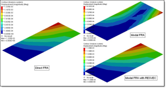
The following image illustrates the effect that the use of the residual vectors has on the result accuracy of the modal frequency response analysis (FRA) compared to the accurate direct method.

The frequency response loads and boundary conditions are defined in the bulk data section of the input deck. They need to be referenced in the subcase information section using an SPC and DLOAD statement in a SUBCASE.
A frequency set must be referenced using a FREQUENCY statement. A METHOD statement is required for the modal method to control the normal modes analysis. In order to save computational effort, previously saved eigenvectors can be retrieved using the EIGVRETRIEVE subcase statement.
In addition to the various damping elements and material damping, uniform structural damping G can be applied using PARAM, G.
Modal damping is being applied using the SDAMPING reference of a damping table TABDMP1. The parameter PARAM, KDAMP is to define the method of applying the damping table.
Frequency-dependent materials (MATFi bulk data entries) can be used in Direct and Modal Frequency Response Analysis, via TABLEDi entries for corresponding fields on the MATi entries. MATF1, MATF2, MATF3, MATF8, MATF9 and MATF10 bulk data entries can be used to define the currently available frequency-dependent materials.
Frequency-dependent properties (PBUSHT bulk data entry) can also be used in Frequency Response Analysis, via TABLEDi entries for the corresponding fields on the PBUSHT entry.
The standard internal solver is used by default for Modal Frequency Response Analysis. However, for some classes for models, improved performance may be obtained by using the Faster Modal Solution Method (FASTFR) or the Fast Frequency Response Solver (FastFRS).
Residual vectors are relevant for modal FRF/acoustics/transient analysis. They enhance the accuracy of these analyses and, hence, are computed by default. You can control RESVEC calculations using the case control statement:
RESVEC(APPLOD/UNITLOD,DAMPLOD/NODAMP)=Value
Where, Value can be Yes or No. The keyword(s) within parentheses are ignored, if the Value specified is No – all RESVEC calculations are turned off. The keyword APPLOD generates RESVECs based on the dynamic loading of the modal FRF/acoustics/transient analysis. The keyword UNITLOD generates RESVECs based on unit loads at the dynamic loading’s degrees of freedom. The keyword DAMPLOD generates viscous damping RESVECs based on unit loads at the viscous damping degrees of freedom. The keyword NODAMP turns off the generation of the viscous damping RESVECs that are otherwise generated by default. Even though DAMPLOD and NODAMP are options in the case control, they are global switches that will be applied to all the modal FRF/acoustics/transient subcases in the model.
When the underlying eigenvalue analysis is done using the Lanczos method, the default RESVECs are generated based on the applied loading and viscous damping degrees of freedom. If the underlying eigenvalue analysis is done using AMSES or AMLS, the default RESVECs are generated based on unit loading at the load degrees of freedom and viscous damping degrees of freedom. Residual vectors are always generated if enforced displacements, velocities or accelerations are defined. In addition, if there is USET U6 data, residual vectors will be calculated if the AMSES or AMLS eigensolver is used. USET U6 residual vectors will not be calculated if the Lanczos eigensolver is used.
When residual vectors are included, inertia relief will be applied by default to unconstrained models. If inertia relief is not desired for RESVECs, it has to be turned off using PARAM, INREL, 0.
When residual vectors are included, the eigenmodes from the underlying eigenvalue analysis of the FRF/transient subcase are used in inertia relief. All modes with eigenvalues below a limit value (FZERO) are used as rigid body modes in the inertia relief analysis. If there are no eigenmodes below FZERO, up to 6 global rigid body modes are internally generated based on the geometry of the model and used in the inertia relief. You can set FZERO using PARAM, FZERO, Value. The default value for FZERO is 0.1.
The results of a frequency response analysis are displacements, velocities, accelerations, forces, stresses, and strains. The usual output entries like STRESS, STRAIN, DISPLACEMENT, etc. can be used to request corresponding output values.
PARAM, ENFMOTN, REL can be used to generate displacement, velocity and acceleration output relative to the specified enforced motion. In such cases, subsequently calculated outputs like stresses and forces are also generated relative to the specified enforced motion. PARAM, ENFMOTN, TOTAL/ABS can be used to generate the total output values including the specified enforced motion (TOTAL/ABS is the default).
Saving and Retrieving Normal Modes Analysis
AMLS (Automatic Multi-Level Sub-structuring) Eigensolver