Linear transient heat transfer analysis can be used to calculate the temperature distribution in a system with respect to time. The applied thermal loads can either be time-dependent or time-invariant; transient thermal analysis is used to capture the thermal behavior of a system over a specific period of time.
The basic finite element equation for transient heat transfer analysis is given by:
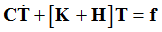
Where, C is the heat capacity matrix, K is the conductivity matrix, H is the boundary convection matrix due to free convection,  is the derivative of the nodal temperature matrix with respect to time, T is the unknown nodal temperature matrix, and f is the thermal loading vector.
The differential equation is solved to find nodal temperature T at the specified time steps. The difference between the equation and the steady-state heat transfer equation is the term,  , that captures the transient nature of the analysis.
Guide to Request a Linear Transient Heat Transfer Analysis
The following steps can be considered as a guide to define the linear transient heat transfer subcase.
| 1. | Use the solution sequence identifier (ANALYSIS) in the subcase information section to select the linear transient heat transfer analysis using: ANALYSIS=HEAT. |
| 2. | Define the time step intervals at which the solutions will be calculated for transient analysis using the TSTEP bulk data entry. This is referenced in the subcase information section by the TSTEP subcase information entry which is used to select the integration type (TSTEP=SID) for transient analysis. |
| 3. | The initial conditions for transient heat transfer analysis are selected by the use of the IC subcase information entry. This entry can be used in the subcase information section to specify the set identification number of the temperature field defined by TEMP or TEMPD bulk data entries. |
| 4. | Use the single point constraint (SPC) data entry to specify the fixed boundary conditions for this analysis. |
| 5. | Use the DLOAD subcase information entry to reference the set ID’s of DLOAD, TLOAD1 and TLOAD2 bulk data entries. Use the TLOAD1 and TLOAD2 bulk data entries to specify: |
(a) Time dependent thermal loading
The EXCITEID field of the TLOAD1 and TLOAD2 bulk data entries should point to the ID’s of QVOL and QBDY1 bulk data entries or a combination of them using LOADADD.
(b) Temperature boundary condition
The EXCITEID field of the TLOAD1 and TLOAD2 bulk data entries should point to the ID of the SPCD bulk data entry. Also, the TYPE field in the TLOAD1 and TLOAD2 entries should be set to 1.
| 6. | The MAT4 and MAT5 bulk data entries can be used to define thermal material properties such as thermal conductivity K, heat capacity C density RHO, convection heat transfer coefficient H and heat generation capability HGEN used in the QVOL data entry. |
| 7. | Heat capacity (CP) is defined on MAT4/MAT5 entries is defined per unit mass. It is multiplied by density (RHO) to calculate heat capacity matrix in transient heat transfer analysis. If RHO is not defined on MAT4/MAT5, then positive density from a structural material entry with matching MID is used. If MAT4/MAT5 entries do not have a corresponding matching structural material, then the default value of 1.0 is used. |
| 8. | The THERMAL I/O option can be used to request nodal temperature output T for transient heat transfer analysis subcases. The FLUX I/O options entry can be used to request temperature gradient and flux output for transient heat transfer analysis subcases. |
Applying Heat Flux Loads
In Step 5(a) of the guide above, the ability to use QBDY1 data to apply heat flux loading is illustrated. This is accomplished as explained in the following steps:
| 1. | The value of the heat flux load is input in the Q0 field of a QBDY1 data entry. |
| 2. | The EID# field in the QBDY1 data entry requires the identification number of CHBDYE surface elements. These surface elements should be created on the surfaces of the model to which heat flux loads are to be applied. |
| 3. | This is conducted in HyperMesh by creating an interface of type CONDUCTION, selecting all the relevant surfaces and then adding CHBDYE surface elements to those surfaces. |
| 4. | These newly created surface elements via the interface group can then be referenced in the EID# field of the QBDY1 data entry. |
Refer to the OS-1090 tutorial for detailed information on setting up heat flux loads and free convection for transient heat transfer analysis.
Note:
| 1. | Shell elements are considered to be membranes in Heat Transfer Analysis. Composite properties are homogenized (1 degree of freedom per grid). The temperature distribution through the thickness of shell elements is not calculated. Only nodal temperature is determined. |
| 2. | Non-zero SPC will be considered as zero SPC for transient thermal analysis, except when non-zero SPC are used to specify ambient points for convection. When an ambient point is controlled by TLOAD1/TLOAD2 via SPCD, the corresponding SPC should be zero. |
Coupled Thermal-structural Analysis
The temperature results from the final time step of a linear transient heat transfer analysis can be applied to a structural subcase. Both TEMPERATURE(LOAD) and TEMPERATURE(MATERIAL) are allowed to reference the subcase ID or temperature result sets from the linear transient heat transfer analysis for use in either material property calculations or thermal loading. If temperatures at multiple time steps are applied to a structural subcase, One Step Transient Thermal Stress Analysis should be used.
See Also:
Results Output
TEMPERATURE
TSTRU


