|
»Click here to display Table of Contents«
|

PCNTX2 |

|

|

|

|
|
PCNTX2 |
|
|

|

|
|
»Click here to display Table of Contents«
|
PCNTX2 |
|
|
|
|
|
PCNTX2 |
|
|
|
|
Bulk Data Entry
PCNTX2 – Extended CONTACT Property type 2 for Geometric Nonlinear Analysis
Description
Defines properties TYPE2 tied CONTACT interface for geometric nonlinear analysis.
Format
(1) |
(2) |
(3) |
(4) |
(5) |
(6) |
(7) |
(8) |
(9) |
(10) |
PCNTX2 |
PID |
|
|
|
|
|
|
|
|
|
IGNROE |
FSPOT |
LEVEL |
ISRCH |
IDELG |
|
|
|
|
If FSPOT = 20, 21, or 22, two continuation lines
(1) |
(2) |
(3) |
(4) |
(5) |
(6) |
(7) |
(8) |
(9) |
(10) |
|
RUPT |
IFILT |
SRTID |
SNTID |
STTID |
|
MAXND |
MAXTD |
|
|
FSTR |
FSTRATE |
FDIST |
ALPHA |
|
|
|
|
|
If FSPOT = 25, one continuation line
(1) |
(2) |
(3) |
(4) |
(5) |
(6) |
(7) |
(8) |
(9) |
(10) |
|
STFAC |
VISC |
|
|
|
|
|
|
|
|
Field |
Contents |
PID |
Property identification number of the associated PCONT. No default (Integer > 0) |
IGNORE |
Flag to ignore slave nodes if no master segment found for TIE contact. See comment 6. Default as defined by CONTPRM (Integer = 0, 1, or 2) 0 - No deletion of slave nodes; |
FSPOT |
Spot weld formulation flag. Default = 5 (Integer) 1 - Formulation is optimized for spot weld or rivets. 20, 21, 22 - formulation with failure. Not compatible with nodal time step GRID(CST) on XSTEP card. The stress is computed for each slave node according to the "equivalent" surface around the node. The equivalent surface is defined accordingly: 20 - Surface computed using shell and brick faces attached to the node. 25 - Penalty formulation. |
LEVEL |
Hierarchy level of the interface. No default (Integer > 0) |
ISRCH |
Search formulation flag for the closest master segment. Default = 2 (Integer) 1 - Old formulation (only used for previous version) 2 - New improved formulation |
IDELG |
Node deletion flag. 0 - No deletion. 1 - The kinematic condition is suppressed on slave node, if the master element is deleted. (The slave node is removed from the interface). |
RUPT |
Failure model (only available with FSPOT = 20, 21, or 22) (Integer). See comment 6. 0 - Failure when MAXND or MAXTD are reached; 1 - See comment 10. |
IFILT |
Filter flag. See comment 12. Default = 0 (Integer = 0 or 1) 0 - No filtering 1 - Filtering (alpha filter) |
SRTID |
TABLEDi entry identification number defining stress factor vs stress rate. See comment 8. No default (Integer > 0) |
SNTID |
TABLEDi entry identification number defining maximum normal stress vs normal relative displacement(ND). This function must be defined. See comment 8. No default (Integer > 0) |
STTID |
TABLEDi entry identification number defining maximum tangential stress vs tangential relative displacement (TD). This function must be defined. See comment 8. No default (Integer > 0) |
MAXND |
Maximum normal relative displacement. Default = 1.0E20 (Real) |
MAXTD |
Maximum tangential relative displacement. Default = 1.0E20 (Real) |
FSTR |
Stress scale factor See comment 8. Default = 1.00 (Real) |
FSTRATE |
Stress rate scale factor. See comment 8. Default = 1.00 (Real) |
FDIST |
Distance scale factor. See comment 8. Default = 1.00 (Real) |
ALPHA |
Stress filter alpha value Default = 1.00 (Real) |
STFAC |
Interface stiffness scale factor. (Only used with FSPOT = 25) Default = 1.00 (Real) |
VISC |
(Optional) Critical damping coefficient on interface stiffness (Only used with FSPOT = 25) Default = 0.05 (Real) |
Comments
| 1. | The property identification number must be that of an existing PCONT bulk data entry. Only one PCNTX2 property extension can be associated with a particular PCONT. |
| 2. | PCNTX2 is only applied in geometric nonlinear analysis subcases which are defined by ANALYSIS = EXPDYN. It is ignored for all other subcases. |
| 3. | PCNTX2 is only valid for tied contact specified using the TIE bulk data entry. The PID field on the TIE entry can be used to reference the PCNTX2 entry. |
| 4. | Interface type 2 is a kinematic condition, no other kinematic condition should be set on any nodes of the slave surface. |
| 5. | The default value for SRCHDIS is the average of the mater segments. |
| 6. | If IGNORE = 1 or 2, the slave nodes without a master segment found during the searching are deleted from the interface; |
If INGORE = 1 and SRCHDIS is blank, then the default value of the distance for searching closest master segment is the average size of the master segments;
If IGNORE = 2 and SRCHDIS is blank, then the distance for searching closest master segment is computed as follows for each slave node:
d1 = 0.6 * (Ts + Tm)
d2 = 0.05 * Tmd
SRCHDIS = max(d1 , d2)
where,
Ts - Thickness of the element connected to the slave node, for solids Ts = 0.0
Tm - Thickness of master segment, for solids Tm = Element volume / Segment area
Tmd - Master segment diagonal
| 7. | Master nodes of an interface type 2 may be slave nodes of another interface type 2 if the hierarchy level of the first interface is lower than the hierarchy level of the second interface. Hierarchy levels are only available with FSPOT=2. |
| 8. | For failure (FSPOT = 20, 21, or 22), it could model glue connection. In this case, the force in slave node will be scaled by reduced force coefficient fN (fT ), which is computed as: |
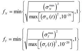
The reduced force is compared to the maximum value:
If ![]() , then ƒN = 1, which means the force will not be reduced.
, then ƒN = 1, which means the force will not be reduced.
If ![]() , then
, then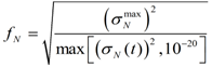 , which means the force will then be reduced.
Here the maximum value will be defined by you with:
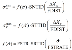
Where,
| Ÿ |
| Ÿ |
| Ÿ |
| Ÿ |
| Ÿ | FSTR is the input constant stress factor |
| Ÿ | SRTID is the input variable coefficient |
| Ÿ | SNTID and STTID are the input stress-displacement tables |
Once the rupture criterion (defined by Rupt) is reached, the contact will be deleted.
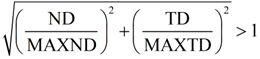
| 9. | If RUPT = 1, the failure criterion is as follows: |
| 10. | If FSPOT = 30, slave mass/inertia/stiffness distribution to the master node is based on the Kirschoff model: bi-cubic form functions are used instead of linear (standard formulation). It allows a softer contact behavior since the element shape curvature is taken into account in the force/moment transmission. |
| 11. | If IDELG = 1, then when a 4-node shell, a 3-node shell or a solid element is deleted, it is also removed from the master side of the interface (kinematic condition is suppressed on relative slave nodes). |
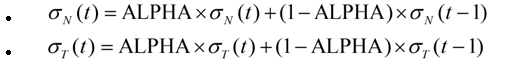
| 12. | If IFILT is set to 1, the normal and tangential stresses are filtered with an alpha filter, as follows: |
| 13. | FSPOT = 25 (penalty formulation) will keep the penalty formulation during the whole run. The slave node (of this contact) could also be the slave node of another kinematic option, like rigid body. The penalty stiffness is constant, calculated as the mean nodal stiffness of master and slave side. The stiffness factor, STFAC, may be used to modify it, if needed. The penalty stiffness will be multiplied by STFAC. A critical viscous damping coefficient (VISC) allows damping to be applied to the interface stiffness. |
See Also: