|
»Click here to display Table of Contents«
|

PCNTX5 |

|

|

|

|
|
PCNTX5 |
|
|

|

|
|
»Click here to display Table of Contents«
|
PCNTX5 |
|
|
|
|
|
PCNTX5 |
|
|
|
|
Bulk Data Entry
PCNTX5 – Extended CONTACT Property type 5 for Geometric Nonlinear Analysis
Description
Defines properties type 5 of a CONTACT interface for geometric nonlinear analysis.
Format
(1) |
(2) |
(3) |
(4) |
(5) |
(6) |
(7) |
(8) |
(9) |
(10) |
PCNTX5 |
PID |
|
|
|
|
IBAG |
IDEL |
|
|
|
STFAC |
FRIC |
GAP |
TSTART |
TEND |
|
|
|
|
|
IBC |
|
IRM |
INACTI |
|
|
|
|
|
|
IFRIC |
IFILT |
FFAC |
|
|
|
|
|
|
|
FRICDAT |
C1 |
C2 |
C3 |
C4 |
C5 |
C6 |
|
|
|
Field |
Contents |
PID |
Property identification number of the associated PCONT. No default (Integer > 0) |
IBAG |
Airbag vent holes closure flag in case of contact. Default = 0 (Integer) 0 - No closure 1 - Closure |
IDEL |
Flag for node and segment deletion. Default as defined by CONTPRM (Integer = 0, 1, or 2) 0 - No deletion. 1 - When all the elements (shells and solids) associated to one segment are deleted, the segment is removed from the master side of the interface. Additionally, non-connected nodes are removed from the slave side of the interface. Has a CPU cost higher than IDEL = 2. 2 - When a shell or a solid element is deleted, the corresponding segment is removed from the master side of the interface. Additionally, non-connected nodes are removed from the slave side of the interface. |
STFAC |
Interface stiffness scale factor. Default = 0.2 (Real > 0) |
FRIC |
Coulomb friction. Default as defined by CONTPRM (Real > 0) |
GAP |
Gap for impact activation (See comment 4). Default as defined by CONTPRM (Real > 0) |
TSTART |
Start time Default = 0.0 (Real > 0) |
TEND |
Time for temporary deactivation. Default = 1030 (Real > 0) |
IBC |
Flag for deactivation of boundary conditions at impact applied to the slave grid set. Default as defined by CONTPRM (Character = X, Y, Z, XY, XZ, YZ, XYZ) |
IRM |
Renumbering flag for segments of the master surface (Integer = 0, 1, or 2). 0 - If segment is connected to a solid element its normal is reversed if entering the solid element (the segment is renumbered). 1 - Normal is always reversed (segment 1234 is read 2143). 2 - Normal is never reversed (segment connected to a solid element are not renumbered). |
INACTI |
Handling of initial penetrations flag (See comment 5). Default as defined by CONTPRM (Integer = 0, 3, or 4) 0 - No action. |
IFRIC |
Friction formulation flag (See comment 6). Default as defined by CONTPRM (Character = COUL, GEN, DARM, or REN) COUL - Static Coulomb friction law. |
IFILT |
Friction filtering flag (See comment 7). Default as defined by CONTPRM (Character = NO, SIMP, PER, or CUTF) NO - No filter is used. |
FFAC |
Friction filtering factor. Default as defined by CONTPRM (Real = 0.0 < FFAC < 1.0) |
FRICDAT |
Indicates that additional information for IFRIC will follow. Only available when IFRIC = GEN, DARM or REN. |
C1, C2, C3, C4, C5, C6 |
Coefficients to define variable friction coefficient in IFRIC = GEN, DARM, or REN. Default as defined by CONTPRM (Real > 0) |
Comments
| 1. | The property identification number must be that of an existing PCONT bulk data entry. Only one PCNTX5 property extension can be associated with a particular PCONT. |
| 2. | PCNTX5 is only applied in geometric nonlinear analysis subcases which are defined by ANALYSIS = NLGEOM or IMPDYN. It is ignored for all other subcases. |
| 3. | If FRIC is not explicitly defined on the PCONTX/PCNTX# entries, the MU1 value on the CONTACT or PCONT entry is used for FRIC in the /INTER entries for Geometric Nonlinear Analysis. Otherwise, FRIC on PCONTX/PCNTX# overwrites the MU1 value on CONTACT/PCONT. |
| 4. | In implicit analysis, different contact formulations are used for contact where slave and master set do not overlap and where they overlap (self-contact). |
In the case of self-contact, the gap cannot be zero and a constant gap is used. For small initial gaps, the convergence will be more stable and faster, if GAP is larger than the initial gap.
In implicit analysis, sometimes a stiffness with scaling factor reduction (for example, STFAC = 0.01) or reduction in impacted thickness (if rigid one) might reduce unbalanced forces and improve convergence, particularly in shell structures under bending where the effective stiffness is much lower than membrane stiffness; but it should be noted that too low of a value could also lead to divergence.
| 5. | INACTI = 3 or 4 are only recommended for small initial penetrations and should be used with caution because: |
| • | the coordinate change is irreversible |
| • | it may create other initial penetrations if several surface layers are defined in the interfaces |
| • | it may create initial energy if the node belongs to a spring element |
| 6. | IFRIC defines the friction model. |
IFRIC = COUL – Coulomb friction with FT < FRIC * FN.
For IFRIC > 0 the friction coefficient is set by a function (µ = µ (p, V)), where p is the pressure of the normal force on the master segment and V is the tangential velocity of the slave node.
The following formulations are available:
| • | IFRIC = 1 - Generalized viscous friction law |
µ = FRIC + C1 * p + C2 * V + C3 * p * v + C4 * p2 + C5 * v2
| • | IFRIC = 2 - Darmstad law |
µ = C1 * e(C2V) * p2 + C3 * e(C4V) * p + C5 * e(C6V)
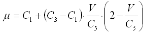
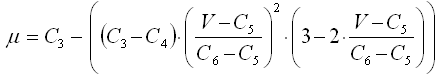
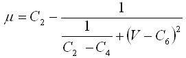
| • | IFRIC = 3 - Renard law |
|
0 < V < C5 |
|
C5 < V < C6 |
|
C6 < V |
where:
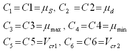
| • | The first critical velocity Vcr1 must not be 0 (C5 ≠ 0). It also must be lower than the second critical velocity Vcr2 (C5 < C6). |
| • | The static friction coefficient C1 and the dynamic friction coefficient C2, must be lower than the maximum friction C3 (C1 < C3 and C2 < C3). |
| • | The minimum friction coefficient C4, must be lower than the static friction coefficient C1 and the dynamic friction coefficient C2 (C4 < C1 and C4 < C2). |
| 7. | IFILT defines the method for computing the friction filtering coefficient. If IFILT ≠ NO, the tangential friction forces are smoothed using a filter: |
FT = α * F'T + (1 - α) * F'T-1
where,
FT is the tangential force
F'T is the tangential force at time t
F'T-1 is the tangential force at time t-1
α is the filtering coefficient
IFILT = SIMP – α = FFAC
IFILT = PER – α = 2![]() dt/FFAC, where dt/T = FFAC, T is the filtering period
dt/FFAC, where dt/T = FFAC, T is the filtering period
IFILT = CUTF – α = 2![]() * FFAC * dt, where FFAC is the cutting frequency
* FFAC * dt, where FFAC is the cutting frequency
| 8. | This card is represented as an extension to a PCONT property in HyperMesh. |
See Also: