|
»Click here to display Table of Contents«
|

PCNTX7 |

|

|

|

|
|
PCNTX7 |
|
|

|

|
|
»Click here to display Table of Contents«
|
PCNTX7 |
|
|
|
|
|
PCNTX7 |
|
|
|
|
Bulk Data Entry
PCNTX7 – Extended CONTACT Property type 7 for Geometric Nonlinear Analysis
Description
Defines properties type 7 of a CONTACT interface for geometric nonlinear analysis.
Format
(1) |
(2) |
(3) |
(4) |
(5) |
(6) |
(7) |
(8) |
(9) |
(10) |
PCNTX7 |
PID |
|
|
|
|
|
|
|
|
|
ISTF |
ITHE |
IGAP |
|
IBAG |
IDEL |
ICURV |
IADM |
|
|
GAPFAC |
GAPMAX |
FPENMAX |
|
|
|
|
|
|
|
STMIN |
STMAX |
MESHSIZE |
DTMIN |
IREMGAP |
|
|
|
|
|
STFAC |
FRIC |
GAP |
TSTART |
TEND |
|
|
|
|
|
IBC |
|
|
INACTI |
VISS |
VISF |
BMULT |
|
|
|
IFRIC |
IFILT |
FFAC |
IFORM |
SENSID |
|
|
|
|
|
CURVDAT |
G1 |
G2 |
|
|
|
|
|
|
|
FRICDAT |
C1 |
C2 |
C3 |
C4 |
C5 |
C6 |
|
|
|
ADMDAT |
NRADM |
PADM |
ANGLADM |
|
|
|
|
|
|
THEDAT |
RTHE |
|
|
TINT |
ITHEF |
|
|
|
|
|
FRAD |
DRAD |
FHEATS |
FHEATM |
|
|
|
|
|
Field |
Contents |
PID |
Property identification number of the associated PCONT. No default (Integer > 0) |
ISTF |
Stiffness definition flag (See comment 5). Default as defined by CONTPRM (Integer = 0, …, 5) 0 - The stiffness is computed according to the master side characteristics. |
ITHE |
Heat contact flag. Default = 0 (Integer) 0 - No heat transfer. 1 - Heat transfer activated. |
IGAP |
Flag for gap definition. Default as defined by CONTPRM (Character = CONST, VAR, VAR2, or VAR3) CONST - Gap is constant and equal to GAP (See comment 6).or VAR3 - Gap is variable (in space, not in time) according to the characteristics of the impacting surfaces and nodes (See comment 7). |
IBAG |
Airbag vent holes closure flag in case of contact. Default = 0 (Integer) 0 - No closure. 1 - Closure. |
IDEL |
Flag for node and segment deletion. Default as defined by CONTPRM (Integer = 0, 1, or 2) 0 - No deletion. 1 - When all the elements (shells, solids) associated to one segment are deleted, the segment is removed from the master side of the interface. Additionally, non-connected nodes are removed from the slave side of the interface. 2 - When a shell or a solid element is deleted, the corresponding segment is removed from the master side of the interface. Additionally, non-connected nodes are removed from the slave side of the interface. |
ICURV |
Gap envelope with curvature (See comment 8). Integer: 0, 1, 2, or 3. 0 - No curvature. 1 - Spherical curvature. 2 - Cylindrical curvature. 3 - Automatic bicubic surface. |
IADM |
Computing local curvature flag for adaptive meshing (See comments 9 and 10). Default = 0 (Integer 0, 1, or 2) 0 - Not activated. 1 - Interface update according mesh size. 2 - Interface update according mesh size, penetration and angle. |
GAPFAC |
Gap scale factor (used only when IGAP = VAR2 and VAR3). Default as defined by CONTPRM (Real > 0) |
GAPMAX |
Maximum gap (used only when IGAP = VAR2 and VAR3). If = 0, there is no maximum value for the gap. Default as defined by CONTPRM (Real > 0) |
FPENMAX |
Maximum fraction of initial penetration (See comment 12). (Real) |
STMIN |
Minimum stiffness (Only with ISTF > 1). Default as defined by CONTPRM (Real > 0) |
STMAX |
Maximum stiffness (Only with ISTF > 1). Default as defined by CONTPRM (Real > 0) |
MESHSIZE |
Percentage of mesh size (used only when IGAP = VAR3). Default = 0.4 (Real, 0.0 < MESHSIZE < 1.0) |
DTMIN |
Limiting nodal time step (see comment 18) |
IREMGAP |
Flag to deactivate slave nodes if element size < gap value, in case of self-impact contact (See comment 19). Default = 1 (Integer) 1 - No slave node deactivation 2 - Deactivate slave nodes. |
STFAC |
Interface stiffness scale factor. Default as defined by CONTPRM (Real > 0) |
FRIC |
Coulomb friction. Default as defined by CONTPRM (Real > 0) |
GAP |
Gap for impact activation (See comments 4 and 6). Default as defined by CONTPRM (Real > 0) |
TSTART |
Start time Default = 0.0 (Real > 0) |
TEND |
Time for temporary deactivation. Default = 1030 (Real > 0) |
IBC |
Flag for deactivation of boundary conditions at impact applied to the slave grid set. Default as defined by CONTPRM (Character = X, Y, Z, XY, XZ, YZ, or XYZ) |
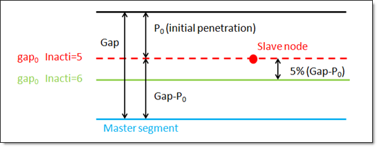
INACTI |
Handling of initial penetrations flag (See comment 12). Default as defined by CONTPRM (Integer = 0, 1, 2, 3, 5, or 6) 0 - No action. 5 - GAP is variable with time and initial gap is adjusted as follows: gap0 = gap - P0 6 - Gap is variable with time but initial gap is slightly de-penetrated as follows: gap0 = gap - P0 – 0.05*(gap - P0) Invalid entries are ignored. |
VISS |
Critical damping coefficient on interface stiffness. Default as defined by CONTPRM (Real > 0) |
VISF |
Critical damping coefficient on interface friction. Default as defined by CONTPRM (Real > 0) |
BMULT |
Sorting factor. Can be used to speed up the sorting algorithm. Is machine-dependent. Default as defined by CONTPRM (Real > 0) |
IFRIC |
Friction formulation flag (See comment 13). Default as defined by CONTPRM (Character = COUL, GEN, DARM, or REN) COUL - Static Coulomb friction law. |
IFILT |
Friction filtering flag (See comment 14). Default as defined by CONTPRM (Character = NO, SIMP, PER, or CUTF) NO - No filter is used. |
FFAC |
Friction filtering factor. Default as defined by CONTPRM (Real = 0.0 < FFAC < 1.0) |
IFORM |
Type of friction penalty formulation (See comment 15). Default as defined by CONTPRM (Character = VISC or STIFF) VISC - Viscous (total) formulation. |
SENSID |
Sensor identifier to Activate/Deactivate the interface (See comment 20). No default (Integer) If a sensor identifier is defined, the activation/deactivation of the interface is based on SENSID instead of TSTART or TSTOP. |
CURVDAT |
Indicates that additional information about ICURV will follow. Only available when ICURV = 1 or 2. |
G1 |
First grid identifier (used only when ICURV = 1 or 2) (Integer) |
G2 |
Second grid identifier (used only when ICURV = 2, ignored when ICURV = 1) (Integer) |
FRICDAT |
Indicates that additional information for IFRIC will follow. Only available when IFRIC = GEN, DARM or REN. |
C1, C2, C3, C4, C5, C6 |
Coefficients to define variable friction coefficient in IFRIC = GEN, DARM, or REN. Default as defined by CONTPRM (Real > 0) |
ADMDAT |
Indicates that additional information about IADM will follow. Only available when IADM = 2. |
NRADM |
Number of elements through a 90 degree radius (used only when IADM = 2). (Integer) |
PADM |
Criteria on the percentage of penetration (used only when IADM = 2). Default = 1.0 (Real) |
ANGLADM |
Angle criteria (used only when IADM = 2) (Real) |
THEDAT |
Indicates that additional information about ITHE will follow. Only available when ITHE = 1. |
RTHE |
Heat conduction coefficient (used only when ITHE = 1, see comment 17) (Real). |
TINT |
Interface temperature (used only when ITHE = 1) (Real) |
ITHEF |
Heat contact formulation flag (used only when ITHE = 1, Integer). 0 - Exchange between constant temperature in the interface and shells (slave side). 1 - Heat exchange between pieces in contact. |
FRAD |
Radiation factor (used only when ITHE = 1) No default (Real) |
DRAD |
Maximum distance for radiation computation (used only when ITHE = 1). A very high value of DRAD is not recommended as it may reduce the performance of the solver. No default (Real) |
FHEATS |
Frictional heating factor of the slave (used only when ITHE = 1, see comment 23) No default (Real) |
FHEATM |
Frictional heating factor of the master (used only when ITHE = 1, see comment 23) No default (Real) |
Comments
| 1. | The property identification number must be that of an existing PCONT bulk data entry. Only one PCNTX7 property extension can be associated with a particular PCONT. |
| 2. | PCNTX7 is only applied in geometric nonlinear analysis subcases which are defined by ANALYSIS = EXPDYN. It is ignored for all other subcases. |
| 3. | If FRIC is not explicitly defined on the PCONTX/PCNTX# entries, the MU1 value on the CONTACT or PCONT entry is used for FRIC in the /INTER entries for Geometric Nonlinear Analysis. Otherwise, FRIC on PCONTX/PCNTX# overwrites the MU1 value on CONTACT/PCONT. |
| 4. | In implicit analysis, different contact formulations are used for contact where slave and master set do not overlap and where they overlap (self-contact). |
In the case of self-contact, the gap cannot be zero and a constant gap is used. For small initial gaps, the convergence will be more stable and faster if GAP is larger than the initial gap.
In implicit analysis, sometimes a stiffness with scaling factor reduction (for example, STFAC = 0.01) or reduction in impacted thickness (if rigid one) might reduce unbalanced forces and improve convergence, particularly in shell structures under bending where the effective stiffness is much lower than membrane stiffness; but it should be noted that too low of a value could also lead to divergence.
| 5. | If ISTF ≠ 1, the interface stiffness K is computed from the master segment stiffness Km and/or the slave segment stiffness Ks. |
The master stiffness is computed from Km = STFAC * B * S * S/V for solids, Km = 0.5 * STFAC * E * t for shells.
The slave stiffness is an equivalent nodal stiffness computed as Ks = STFAC * B * V-3 for solids, Ks = 0.5 * STFAC * E * t for shells.
In these equations, B is the Bulk Modulus, S is the segment area, and V is the volume of a solid. There is no limitation to the value of stiffness factor (but a value larger than 1.0 can reduce the initial time step).
The interface stiffness is then K = max (STMIN, min (STMAX, K1)) with:
| • | ISTF = 0, K1 = Km |
| • | ISTF = 2, K1 = 0.5 * (Km + Ks) |
| • | ISTF = 3, K1 = max (Km, Ks) |
| • | ISTF = 4, K1 = min (Km, Ks) |
| • | ISTF = 5, K1 = Km * Ks / (Km + Ks) |
| 6. | The default for the constant gap (IGAP = CONST) is the minimum of: |
| • | t, average thickness of the master shell elements |
| • | l/10, l – average side length of the master solid elements |
| • | lmin/2, lmin – smallest side length of all master segments (shell or solid) |
| 7. | If IGAP = VAR, the variable gap is computed as gs + gm |
If IGAP = VAR2, the variable gap is computed as max(GAP, min(GAPFAC * (gs+gm), GAPMAX)
If IGAP = VAR3, the variable gap is computed as max(GAP, min(GAPFAC * (gs+gm), MESHSIZE * (gsl+gml), GAPMAX)
with:
| • | gm - master element gap, with: |
gm = t/2, t: thickness of the master element for shell elements.
gm = 0 for solid elements.
| • | gs - slave node gap: |
gs = 0 if the slave node is not connected to any element or is only connected to solid or spring elements.
gs = t/2, t - largest thickness of the shell elements connected to the slave node.
gs = 1/2√S for truss and beam elements, with S being the cross section of the element.
| • | gml - length of the smaller edge of element. |
| • | gsl - length of the smaller edge of elements connected to the slave nodes. |
If the slave node is connected to multiple shells and/or beams or trusses, the largest computed slave gap is used.
The variable gap is always at least equal to GAP.
| 8. | If ICURV = 1, a spherical curvature is defined for the gap with node_ID1 (center of the sphere). |
If ICURV = 2, a cylindrical curvature is defined for the gap with node_ID1 and node_ID2 (on the axis of the cylinder).
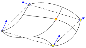
If ICURV = 3, the master surface shape is obtained with a bicubic interpolation, respecting continuity of the coordinates and the normal from one segment to the other.
In case of a large change in curvature, this formulation might become unstable (will be improved in future version).
| 9. | In case of adaptive meshing and IADM =1: |
If the contact occurs in a zone (master side) whose radius of curvature is lower than the element size (slave side), the element on the slave side will be divided (if not yet at maximum level).
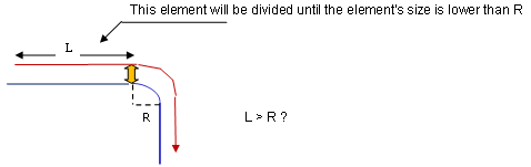
| 10. | In case of adaptive meshing and IADM =2: |
If the contact occurs in a zone (master side) whose radius of curvature is lower than NRadm times the element size (slave side), the element on the slave side will be divided (if not yet at maximum level).
If the contact occurs in a zone (master side) where the angles between the normals are greater than Angladm and the percentage of penetration is greater than Padm, the element on the slave side will be divided (if not yet at maximum level).

| 11. | The coefficients NRADM, PADM, and ANGLADM are used only adaptive meshing and IADM = 2. |
| 12. | INACTI = 3, is only recommended for small initial penetrations and should be used with caution because: |
| • | the coordinate change is irreversible |
| • | it may create other initial penetrations if several surface layers are defined in the interfaces |
| • | it may create initial energy if the node belongs to a spring element |
INACTI = 5 is recommended for airbag simulation deployment.
INACTI = 6 is recommended instead of INACTI = 5, in order to avoid high frequency effects into the interfaces.
If FPENMAX is not equal to zero, nodes stiffness is deactivated if penetration > FPENMAX*GAP, regardless of the value of INACTI.
| 13. | IFRIC defines the friction model. |
IFRIC = COUL – Coulomb friction with FT < FRIC * FN.
For IFRIC > 0 the friction coefficient is set by a function (![]() =
= ![]() (p, V)), where p is the pressure of the normal force on the master segment and V is the tangential velocity of the slave node.
(p, V)), where p is the pressure of the normal force on the master segment and V is the tangential velocity of the slave node.
The following formulations are available:
| • | IFRIC = 1 - Generalized viscous friction law |
![]() = FRIC + C1 * p + C2 * V + C3 * p * v + C4 * p2 + C5 * v2
= FRIC + C1 * p + C2 * V + C3 * p * v + C4 * p2 + C5 * v2
| • | IFRIC = 2 - Darmstad law |
![]() = C1 * e(C2V) * p2 + C3 * e(C4V) * p + C5 * e(C6V)
= C1 * e(C2V) * p2 + C3 * e(C4V) * p + C5 * e(C6V)
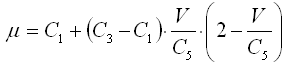
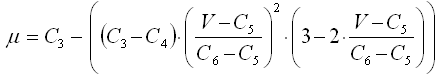
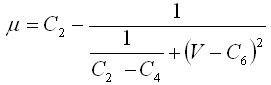
| • | IFRIC = 3 - Renard law |
|
0 < V < C5 |
|
C5 < V < C6 |
|
C6 < V |
where:
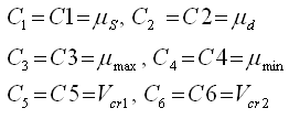
| • | The first critical velocity Vcr1 must not be 0 (C5 ≠ 0). It also must be lower than the second critical velocity Vcr2 (C5 < C6). |
| • | The static friction coefficient C1 and the dynamic friction coefficient C2, must be lower than the maximum friction C3 (C1 < C3) and C2 < C3). |
| • | The minimum friction coefficient C4, must be lower than the static friction coefficient C1 and the dynamic friction coefficient C2 (C4 < C1 and C4 < C2). |
| 14. | IFILT defines the method for computing the friction filtering coefficient. If IFILT ≠ NO, the tangential friction forces are smoothed using a filter: |
FT = α * F'T + (1 - α) * F'T-1
where,
FT is the tangential force
F'T is the tangential force at time t
F'T-1 is the tangential force at time t-1
α is the filtering coefficient
IFILT = SIMP – α = FFAC
IFILT = PER – α = 2![]() dt/FFAC, where dt/T = FFAC, T is the filtering period
dt/FFAC, where dt/T = FFAC, T is the filtering period
IFILT = CUTF – α = 2![]() * FFAC * dt, where FFAC is the cutting frequency
* FFAC * dt, where FFAC is the cutting frequency
| 15. | IFORM selects two types of contact friction penalty formulation. |
The viscous (total) formulation (IFORM = VISC) computes an adhesive force as:
Fadh = VISF * √(2KM) * VT
FT = min (μFN, Fadh)
The stiffness (incremental) formulation (IFORM = STIFF) computes an adhesive force as:
Fadh = FTold + ![]() FT
FT
![]() FT = K * VT * dt
FT = K * VT * dt
FTnew = min (μFN, Fadh)
| 16. | Exchange between shell and constant temperature contact TINT. |
| 17. | RTHE is the inverse of thermal resistance (units: [W/(m2·K)]). |
| 18. | Slave segment contact is deactivated when the segment kinematic time step calculated for this contact is lower than DTMIN. |
| 19. | With IREMGAP = 2, this allows the element size < gap values: |

In case of self-impact contact, when curvilinear distance (from a node of the master segment to a slave node) is < gap*sqrt(2) (in initial configuration), then this slave node will not be taken into account by this master segment, and it will not be deleted from the contact for the other master segments.
| 20. | When SENSID is defined for activation/deactivation of the interface, TSTART and TSTOP are not taken into account. |
| 21. | If FRAD is not equal to zero, and d, the distance from the slave node to the master segment, is in the range: Gap < d < DRAD, then radiation is calculated. The radiant heat transfer conductance is calculated as: |
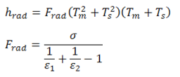
Where, ![]() is the Stefan Boltzman constant,
is the Stefan Boltzman constant, ![]() is the emissivity of the slave surface, and
is the emissivity of the slave surface, and ![]() is the emissivity of the master surface.
is the emissivity of the master surface.
| 22. | If FRAD is not equals to zero, then the default value of DRAD is calculated as the maximum of: |
| • | upper value of the gap (at time 0) among all nodes |
| • | smallest side length of slave element |
| 23. | Frictional energy is converted into heat when heat transfer is activated (ITHE > 0) on the interface. Options FHEATS and FHEATM are used to control this option. |
When FHEATS and FHEATM = 0, the conversion of the frictional sliding energy to heat is not activated. Non-zero values of FHEATS and FHEATM define the fraction of this energy which is converted into heat and transferred to the slave and master respectively.
The frictional heat QFric is defined as follows:
If IFORM = 2 (a stiffness formulation):
Slave: ![]()
Master: ![]() (ITHEF=1)
(ITHEF=1)
If IFORM = 1 (a penalty formulation):
Slave: ![]()
Master: ![]() (ITHEF=1)
(ITHEF=1)
| 24. | This card is represented as an extension to a PCONT property in HyperMesh. |
See Also: