|
»Click here to display Table of Contents«
|

PCNTX11 |

|

|

|

|
|
PCNTX11 |
|
|

|

|
|
»Click here to display Table of Contents«
|
PCNTX11 |
|
|
|
|
|
PCNTX11 |
|
|
|
|
Bulk Data Entry
PCNTX11 – Extended Contact (CONTX11) Property type 11 for Geometric Nonlinear Analysis
Description
Defines properties type 11 of a CONTACT interface for geometric nonlinear analysis.
Format
(1) |
(2) |
(3) |
(4) |
(5) |
(6) |
(7) |
(8) |
(9) |
(10) |
PCNTX11 |
PID |
|
ISTF |
|
IGAP |
|
|
IDEL |
|
|
STMIN |
STMAX |
MESHSIZE |
DTMIN |
|
|
|
|
|
|
STFAC |
FRIC |
GAP |
TSTART |
TEND |
STF1 |
|
|
|
|
IBC |
|
|
INACTI |
VISS |
VISF |
BMULT |
|
|
|
Field |
Contents |
PID |
Property identification number of the associated PCONT. No default (Integer > 0) |
ISTF |
Stiffness definition flag (See comment 5). Default as defined by CONTPRM (Integer = 0, …, 5) 0 - STFAC is a stiffness scale factor and the stiffness is computed according to the master side characteristics. |
IGAP |
Gap definition flag. Default as defined by CONTPRM (Character = CONST, VAR, or VAR3) CONST - Gap is a constant and equal to GAP. VAR - Gap is a variable (in space, not in time) according to the characteristics of the impacted master line and the impacting slave nodes (See comment 6). VAR3 - Gap is a variable according to the characteristics of the impacted master line and impacting slave node + gap is taken into account the size of the elements. |
IDEL |
Flag for node and segment deletion. Default as defined by CONTPRM (Integer = 0, 1, or 2) 0 - No deletion. 1 - When all the elements (shells and solids) associated to one segment are deleted, the segment is removed from the master side of the interface. Additionally, non-connected nodes are removed from the slave side of the interface. 2 - When a shell or a solid element is deleted, the corresponding segment is removed from the master side of the interface. Additionally, non-connected nodes are removed from the slave side of the interface. |
STMIN |
Minimum stiffness (Only with ISTF > 1). Default as defined by CONTPRM (Real > 0) |
STMAX |
Maximum stiffness (Only with ISTF > 1). Default as defined by CONTPRM (Real > 0) |
MESHSIZE |
Percentage of mesh size (Used only when IGAP = VAR3). Default = 0.4 (Real, 0.0 < MESHSIZE < 1.0) |
DTMIN |
Limiting nodal time step (see comment 10) No default (Real > 0) |
STFAC |
Interface stiffness scale factor (Only with ISTF ≠ 1). Default as defined by CONTPRM (Real > 0) |
FRIC |
Coulomb friction. Default as defined by CONTPRM (Real > 0) |
GAP |
Gap for impact activation (See comment 6). Default as defined by CONTPRM (Real > 0) |
TSTART |
Start time. Default = 0.0 (Real > 0) |
TEND |
Time for temporary deactivation. Default = 1030 (Real > 0) |
STIF1 |
Interface stiffness (Only with ISTF = 1). Default = 0.0 (Real > 0) |
IBC |
Flag for deactivation of boundary conditions at impact applied to the slave grid set. Default as defined by CONTPRM (Character = X, Y, Z, XY, XZ, YZ, or XYZ) |
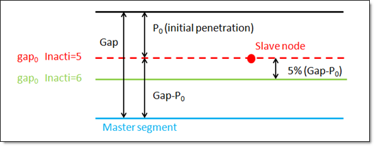
INACTI |
Handling of initial penetrations flag (See comment 7). Default as defined by CONTPRM (Integer = 0, 1, 2, 3, 5, or 6) 0 - No action. gap0 = gap - P0 6 - Gap is variable with time but initial gap is slightly de-penetrated as follows: gap0 = gap - P0 – 0.05*(gap - P0) Invalid entries are ignored. |
VISS |
Critical damping coefficient on interface stiffness. Default as defined by CONTPRM (Real > 0) |
VISF |
Critical damping coefficient on interface friction. Default as defined by CONTPRM (Real > 0) |
BMULT |
Sorting factor. Can be used to speed up the sorting algorithm and is machine-dependent. Default as defined by CONTPRM (Real > 0) |
Comments
| 1. | The property identification number must be that of an existing PCONT bulk data entry. Only one PCNTX11 property extension can be associated with a particular PCONT. |
| 2. | PCNTX11 is only applied in geometric nonlinear analysis subcases which are defined by ANALYSIS = EXPDYN. It is ignored for all other subcases. |
| 3. | If FRIC is not explicitly defined on the PCONTX/PCNTX# entries, the MU1 value on the CONTACT or PCONT entry is used for FRIC in the /INTER entries for Geometric Nonlinear Analysis. Otherwise, FRIC on PCONTX/PCNTX# overwrites the MU1 value on CONTACT/PCONT. |
| 4. | PCNTX11 defines the properties of contact interface type CONTX11, it describes the edge to edge or line to line interface. This interface simulates impact between lines, a line can be a beam or truss element or a shell edge or spring elements. The interface properties are: |
| • | impacts occur between a master and a slave line |
| • | a slave line can impact on one or more master lines |
| • | a line can belong to the master and the slave side. This allows self impact. |
| • | this interface can be used in addition to the interface type 7 PCNTX7 to solve the edge to edge limitation of interface type 7 |
| 5. | If ISTF ≠ 1, the interface stiffness K is computed from the master segment stiffness Km and/or the slave segment stiffness Ks. |
The master stiffness is computed from Km = STFAC * B * S * S/V for solids, Km = 0.5 * STFAC * E * t for shells.
The slave stiffness is an equivalent nodal stiffness computed as Ks = STFAC * B * V-3 for solids, Ks = 0.5 * STFAC * E * t for shells.
In these equations, B is the Bulk Modulus, S is the segment area, and V is the volume of a solid. There is no limitation to the value of stiffness factor (but a value larger than 1.0 can reduce the initial time step).
The interface stiffness is K = max (STMIN, min (STMAX, K1)) with:
| • | ISTF = 0, K1 = Km |
| • | ISTF = 2, K1 = 0.5 * (Km + Ks) |
| • | ISTF = 3, K1 = max (Km, Ks) |
| • | ISTF = 4, K1 = min (Km, Ks) |
| • | ISTF = 5, K1 = Km * Ks / (Km + Ks) |
| 6. | If IGAP = VAR, the variable gap is computed as: gm + gs |
with:
| • | gm - master element gap with |
gm = t/2, t: thickness of the master element for shell elements.
gm = L/10, L - length of the smallest side of a solid element.
gm = 1/2√ for truss and beam elements, with S being the cross section of the element.
gm = 0 for spring elements.
| • | gs - slave element gap is computed as the same way. |
If the slave node is connected to multiple shells and/or beams or trusses, the largest computed slave gap is used.
The variable gap is always at least equal to GAP.
| 7. | INACTI = 3, is only recommended for small initial penetrations and should be used with caution because: |
| • | the coordinate change is irreversible |
| • | it may create other initial penetrations, if several surface layers are defined in the interfaces |
| • | it may create initial energy, if the node belongs to a spring element |
INACTI = 5 is recommended for airbag simulation deployment.
INACTI = 6 is recommended instead of INACTI = 5, in order to avoid high frequency effects into the interfaces.
| 8. | Slave segment is deactivated from the contact when the segment kinematic time step calculated for this contact becomes smaller than DTMIN. |
See Also: