|
»Click here to display Table of Contents«
|

PEAKOUT |

|

|

|

|
|
PEAKOUT |
|
|

|

|
|
»Click here to display Table of Contents«
|
PEAKOUT |
|
|
|
|
|
PEAKOUT |
|
|
|
|
Bulk Data Entry
PEAKOUT – Peak Identification Criteria
Description
Defines criteria used for the automatic identification of loading frequencies at which result peaks occur. Other result output may then be requested at these “peak” loading frequencies. This feature is only supported for frequency response solution sequences.
Format
(1) |
(2) |
(3) |
(4) |
(5) |
(6) |
(7) |
(8) |
(9) |
(10) |
PEAKOUT |
SID |
NPEAK |
NEAR |
FAR |
LFREQ |
HFREQ |
RTYPE |
PSCALE |
|
|
GRIDC |
GID1 |
CID1 |
CUTOFF1 |
GID2 |
CID2 |
CUTOFF2 |
|
|
|
|
GID3 |
CID3 |
CUTOFF3 |
... |
... |
... |
|
|
|
|
... |
... |
|
|
|
|
|
|
|
Field |
Contents |
|---|---|
SID |
Set identification number. No default (Integer > 0) |
NPEAK |
Desired number of peaks. See comment 2. Default = 5 (Integer > 0) |
NEAR |
Minimum allowed distance between two peaks. If two peaks are closer than this value, the loading frequency of the lower peak will be ignored. See comment 2. Default = 0.0 (Real > 0.0) |
FAR |
Maximum allowed distance between two peaks. Additional peaks will be selected (in addition to NPEAK) if the distance between the peaks is greater than this value. See comment 2. Default = largest applied loading frequency (Real > 0.0) |
LFREQ |
Starting loading frequency for peak identification. See comment 2. Default = 0.0 (Real > 0.0) |
HFREQ |
Ending loading frequency for peak identification. See comment 2. Default = largest applied loading frequency (Real > 0.0) |
RTYPE |
Result type for peak identification for the structural domain. The result for a structural degree of freedom can be displacement (DISP), velocity (VELO), or acceleration (ACCE). Default = DISP (DISP, VELO or ACCE) |
PSCALE |
Pressure scaling method for peak identification for the fluid domain. The result for a fluid grid can be the scale of pressure, decibels (DB) or A-weighted decibels (DBA). See comment 3 for decibel calculations and reference pressure settings. For DBA, standard A-weighting is used. Default = DBA (DB, DBA or NONE) |
GRIDC |
Indicates that a degree-of-freedom list for peak identification is to follow. |
GID# |
Grid identification number. No default (Integer > 0) |
CID# |
Component identification number. No default (1 < Integer < 6) |
CUTOFF# |
The cutoff value can be a real value or an integer value. See comment 2. If the entry is a real value, then this is the value of the cutoff (in the same unit specified by RTYPE and PSCALE). If the entry is an integer value, then this is the identification number of a TABLED1, TABLED2, TABLED3, or TABLED4 entry defining the cutoff as a function of frequency (in the same unit specified by RTYPE and PSCALE). Default = 0.0 (Real or Integer > 0) |
| 1. | There can be multiple PEAKOUT cards with the same SETID. |
| 2. | The following example shows how the different criteria work in identifying peaks. |
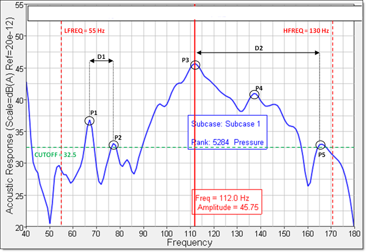
Figure 1: Plot of the Acoustic Response vs. Frequency
Figure 1 shows a plot of the Acoustic Response versus frequency for a chosen degree-of-freedom. The total frequency range can be reduced to the frequency range of interest by defining LFREQ and HFREQ. The search area can be further reduced by defining CUTOFF such that low magnitude peaks can be ignored. In the remaining region, 5 peaks (P1, P2, P3, P4, and P5) can easily be identified. Should NPEAK be set to 4, the resulting frequency set would consist of the frequencies corresponding to the peaks P4, P2, P1, and P3, with P5 being omitted.
In order to ensure that peaks are neither too far apart nor too close together, the FAR and NEAR criteria, respectively, may be used.
In the above example, should a value of 50HZ be defined for FAR, P4 would be selected in addition to the other peaks because D2 (~54 Hz) is greater than 50Hz, and so an additional peak is required to satisfy the FAR criterion.
Similarly, should a value of 15Hz be defined for NEAR, then P2 will be omitted, as D1 (~11 Hz) is less than 15Hz.
| 3. | The dB value is calculated using 20 * log10 (P/P0), where P0 is the reference pressure. The reference pressure is dependent on the units specified on the UNITS input data. If the units are SI, the value is set as 2.0E-5 Pa. If they are CGS, it is set as 2.0E-4 barye. If they are MPa, it is set as 2.0E-11 MPa. If they are BG or EE, then it is set as 4.17E-7 lbf/ft2. If no UNITS data is present, the default value is 2.0E-11 MPa. |
| 4. | If you wish to include interior points of a superelement (in a CMS model) for the purposes of peak identification using the PEAKOUT bulk data entry, the SEINTPNT entry can be used in the subcase information section to convert the interior grid points to exterior grid points (since points referenced by PEAKOUT should be exterior points only). |
See Also: