Overview
Many engineering assemblies are put together using bolts, which are usually pretensioned before application of working loads. A typical sequence is described below.
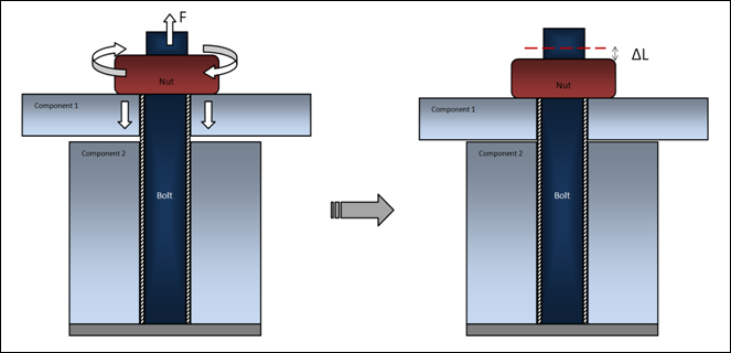
Figure 1: Step 1 of pretensioned assembly - application of pretensioning loads
In Step 1, upon preliminary assembly of the structure, the nuts on respective bolts are tightened, usually by applying specified torque (which translates into specified tension force according to the pitch of the thread).
As the result, the working part of the bolt becomes shorter by a distance  . This distance depends upon the applied force, the compliance of the bolt and of the assembly being pretensioned.
From the perspective of FEA analysis, it is important to recognize that:
| • | Pretensioning actually shortens the working part of the bolt by removing a certain length of the bolt from the active structure (in reality this segment slides through the nut, yet the net effect is the shortening of the working length of the bolt). At the same time the bolt stretches, since now the smaller effective length of the bolt material has to span the distance from the bolt mount to the nut. |
| • | Calculation of each bolt’s shortening  , due to applied forces f, requires FEA solution of the entire model with the pretensioning forces applied. This is because the amount of nut movement due to given force depends on the compliance of the bolts, of the assembly being bolted and is also affected by cross-interaction between multiple bolts being pretensioned. , due to applied forces f, requires FEA solution of the entire model with the pretensioning forces applied. This is because the amount of nut movement due to given force depends on the compliance of the bolts, of the assembly being bolted and is also affected by cross-interaction between multiple bolts being pretensioned. |
At the end of Step 1, the amount of shortening  for each bolt is established and “locked”, simply by leaving the nuts at the position that they reached during the pretensioning step.
In Step 2, with the shortening  of all the bolts “locked”, other loads are applied to the assembly (Figure 2). At this stage the stresses and strains in the bolts will usually change, while the length of material removed
  remains constant for each bolt.
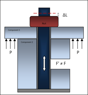
Figure 2: Step 2 of pretensioned assembly – application of working loads with “locked” bolt shortening
Comments
In practice, there may be variations of the application of pretensioning loads and more complex pretensioning sequences than that presented above. For example:
In alternative assembly scenarios, instead of using a nut on top of the bolt, the bolt may be screwed into a base and thus compress the assembly, as illustrated in Figure 3.
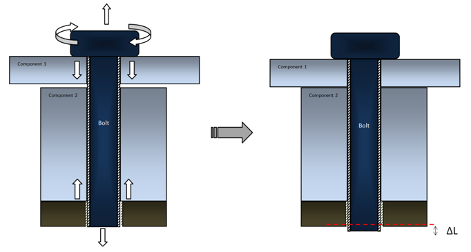
Figure 3: An alternative approach to application of pretensioning loads
In this case, the shortening (removal of material) of the working part of the bolt happens at the thread within the base, rather than at the bolt-nut interface. Yet the final mechanical effect is the same.
Sometimes the pretensioning by torque/force is augmented by “tightening” via specified number of turns. This means that on top of the  , due to pretensioning force, an additional
  ’ is added according to the number of turns and the pitch of the thread.
In an automated assembly process, usually all bolts are pretensioned simultaneously. Sometimes, however, the tensioning may happen in sequence or in groups. In such cases, while  is “locked” for bolts that have already been pretensioned, consecutive pretensioning force is applied to the next batch of bolts, which then become “locked” for the following step.
FEA Solution with Pretensioning
In analysis of structures, the FEA model is usually defined in material reference frame and the amount of material is assumed to remain fixed, while the structure undergoes stretching and deformation. However, in the case of pretensioning, the actual working part of the model has some material removed by being driven through the nut (usually the protruding part of the bolt is not included in the working FEA model, since it does not participate in the balance of forces on the structure).
The simulation of this phenomenon in Optistruct follows the approach described below:
First, it is recognized that for straight bolts, from the viewpoint of balance of forces it does not matter at what location the removal of the material happens in the bolt. Therefore, instead of simulating the precise interaction between the nut and the bolt, the pretensioning is handled within the length of the bolt. Pretensioning in OptiStruct is implemented with the help of Multiple Point Constraints (MPC’s) via two different processes:
Multiple point constraints (MPC’s) are used in both 1D and 3D pretensioning, the difference between the two implementations is the number of duplicate grid points created and controlled via MPC’s.
1D Bolt Pretensioning
In this process, the bolt or its selected section is represented by single or multiple 1D element(s) (beam or rod).
| Note: | If a bolt is meshed with 3D (solid) elements, 1D pretensioning can be applied by replacing a transverse section of the bolt with 1D beam/rod elements. In such cases; however, 3D pretensioning is recommended since it is easier to implement and accuracy is improved. If a bolt is constructed using 1D elements, 1D pretensioning can be used effectively. |
|
Step 1
The conceptual FEA handling of 1D bolt pretensioning is illustrated in Figure 4. A bolt is modeled using 3D elements and a beam or rod element represents the selected section of the bolt where pretensioning will be applied.
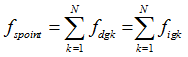
| 1. | First, an imaginary cut is introduced into the beam (This is automatically done internally for a subcase that includes a PRETENSION command) and two duplicate grid points are created at the location of the cut. |
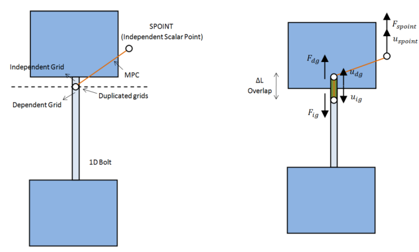
Figure 4: FEA implementation of Bolt Pretensioning applied to a 1D Bolt using a 1D element
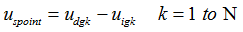
Additionally, a scalar point (SPOINT) is automatically created to act as an independent grid point. A pair of self-balanced pretensioning forces is applied to both ends of the cut with the help of the newly created SPOINT. The specified pretensioning force is internally applied on the SPOINT and this is transferred to the duplicated grid points via an MPC. The MPC controls the movement of the newly created duplicate grid points and the scalar point based on the following equation:
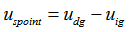
Where,  is the displacement of the independent scalar point (SPOINT),
  is the displacement of the dependent grid point, and
  is the displacement of the independent grid point.
The reaction force on the scalar point due to an enforced displacement of  on it can be shown to be equal to the forces acting on the dependent or independent grid point.
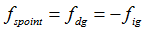 or
or 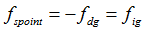 depending on the direction of the forces.
Where,  is the total reaction force on the independent scalar point (SPOINT) due to an enforced displacement of
  ,
,  is the force acting on the dependent grid point, and
  is the force acting on the independent grid point.
| 2. | With these forces (plus other loads referenced in this subcase) applied, static analysis is performed to calculate deformation of the structure. Among the results of such analysis is the “overlap”  across the cut portion of the beam, which is equivalent to the distance that the bolt would move relative to the nut in Figure 1. across the cut portion of the beam, which is equivalent to the distance that the bolt would move relative to the nut in Figure 1. |
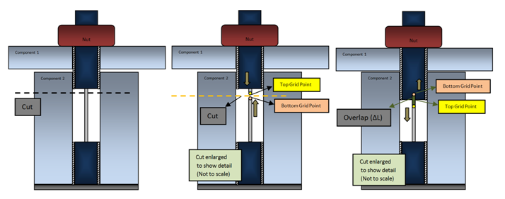
Figure 5: FEA implementation of Bolt Pretensioning applied to a 3D Bolt using a 1D element (Step 1)
Step 2
As shown in Figure 5, the amount of overlap  calculated in Step 1 is removed from the bolt length, and the bolt is reconnected at the cut location. This represents the shorter working length of a pretensioned bolt on which the nut has been tightened (Mechanically, this is similar to the effect of the DEFORM command).
With bolt pretensioning “locked” in this way, additional working loads are applied and a FEA solution is performed.
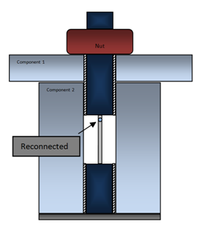
Figure 6: FEA implementation of Bolt Pretensioning applied to a 3D Bolt using a 1D element (Step 2)
As mentioned already, it is possible to construct more complex sequences of pretensioning, wherein some bolts have already been pretensioned (Step 2) while the next batch of bolts is being pretensioned (Step 1). (Note that a specific tensioning sequence has an effect on the final result only in path-dependent problems, such as contact with friction or elasto-plastic materials.)
3D Bolt Pretensioning
In 3D Bolt Pretensioning, the bolt is represented (meshed) using 3D solid elements. A transverse surface in the beam is identified (cross-section) along which it is cut and the duplicate grids are then controlled by Multiple Point Constraints (MPC’s) and a SPOINT to simulate the pretensioning effect.
Step 1
The first step in 3D pretensioning is to identify the transverse cross-sectional surface of the bolt. OptiStruct automatically cuts the bolt at the selected surface and duplicate grid points are created mirroring the existing grid points at the cut surface. This is automatically done internally for a subcase that includes a PRETENSION command.
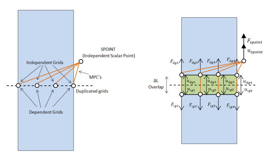
Figure 7: FEA implementation of Bolt Pretensioning applied to a 3D Bolt using a 3D element (Pretension Direction)
Additionally, a scalar point (SPOINT) is automatically created to act as an independent grid point. A pair of self-balanced pretensioning forces is applied to both ends of the cut with the help of the newly created SPOINT. The specified pretensioning force is internally applied on the SPOINT and this is transferred to the duplicated grid points via MPC’s. The MPC’s controls the movement of the newly created duplicate grid points and the scalar point based on the following equations:
In the pretension direction:
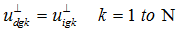
Perpendicular to the pretension direction:
Where,  is the displacement of the independent scalar point (SPOINT),
  is the displacement of the k’th dependent grid point,
  is the displacement of the k’th independent grid point, N is the displacement of the k’th independent grid point,
  is the displacement of the k’th dependent grid point perpendicular to the pretension direction, and
  is the displacement of the k’th independent grid point perpendicular to the pretension direction.
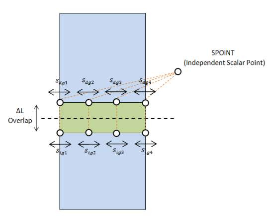
Figure 8: FEA implementation of Bolt Pretensioning applied to a 3D Bolt using a 3D element (Perpendicular to the Pretension Direction)
The reaction force on the scalar point due to an enforced displacement of  on it can be shown to be equal to the sum of the magnitudes of the forces acting on either the dependent or independent grid points.
Where,  is the total reaction force on the independent scalar point (SPOINT) due to an enforced displacement of
  ,
,  is the force acting on the k’th dependent grid point, and
  is the force acting on the k’th independent grid point.
When these forces (including other loads referenced in this subcase) are applied, static analysis is performed to calculate deformation of the structure. Among the results of such analysis is the “overlap”  across the cut portion of the bolt, which is equivalent to the distance that the bolt would move relative to the nut.
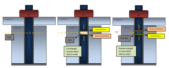
Figure 9: FEA implementation of Bolt Pretensioning applied to a 3D Bolt using a 3D element (Step 1)
Step 2
As shown in Figure 5, the amount of overlap  calculated in Step 1 is removed from the bolt length, and then the bolt is reconnected at the initial cut surface. This represents the shorter working length of a pretensioned bolt on which the nut has been tightened. (Mechanically, this is similar to the effect of the DEFORM command.)
With bolt pretensioning “locked” in this way, additional working loads are applied and FEA solution is performed.
Figure 10: FEA implementation of Bolt Pretensioning applied to a 3D Bolt using a 3D element (Step 2)
As mentioned earlier (in 1D pretensioning), it is possible to construct complex pretensioning sequences wherein some bolts have already been pretensioned (Step 2) while the next batch of bolts is being pretensioned (Step 1).
| Note: | A specific tensioning sequence has an effect on the final result only in path-dependent problems, such as contact with friction or elasto-plastic materials. |
|
Analysis of Pretensioned Assemblies in OptiStruct
In OptiStruct, the solution of problems involving pretensioning fits into the standard sequences of static subcases, linear or nonlinear. (Step 2, analysis of pretensioned structure, is also available in natural frequency, frequency response, buckling and transient subcases).
Respective user’s input requires definition of pretensioning sections, loads and adjustments in the Bulk Data section, plus specification of tensioning sequences in the Subcase section. The available commands are outlined below – for more details, see individual card descriptions.
Bulk Data Section
PRETENS
|
Defines the pretension section. Presently this identifies the respective 1D element.
|
PTFORCE
|
Defines the pretensioning force F (actually a pair of forces) and assigns it to the respective pretension section.
|
PTFORC1
|
A simplified format that allows assigning force to multiple pretension sections.
|
PTADJST
|
Defines the tensioning adjustment  L’ and assigns it to the respective pretension section. L’ and assigns it to the respective pretension section.
|
PTADJS1
|
A simplified format that allows assigning one adjustment amount to multiple pretension sections.
|
PTADD
|
Combines multiple pretensioning forces or adjustments into a single load ID.
|
PRETPRM, INILOAD
|
See the parameter page for more information.
|
PRETPRM, PRTSW
|
See the parameter page for more information.
|
Subcase Section
PRETENSION
|
Identifies pretensioning forces/adjustments to be activated in this static subcase. (Corresponds to Step 1 described above.)
|
STATSUB
(PRETENS)
|
Identifies the static subcase that created pretensioned bolts, which are to be included in the present subcase. (Corresponds to Step 2 described above.)
|
It is allowed to have PRETENSION and STATSUB(PRETENS) in the same static subcase – this can be used to emulate more complex pretensioning sequences.
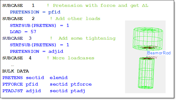
A Simple Illustration
A simple illustration of typical flow of pretensioned analysis is shown below. This is not a complete input deck, merely an illustration of a typical arrangement of respective commands. Refer to the tutorial OS-1390: 1D and 3D Pretensioned Bolt Analysis of an IC Engine Cylinder Head, Gasket and Engine Block System Connected Using Head Bolts for more information on setting up 1D and 3D pretensioned analysis.
Comments
Subcases that Support Pretensioning
Pretensioning Steps 1 and 2 require the solution of a static FEA problem. Therefore, PRETENSION and STATSUB(PRETENS) commands can appear only in linear or nonlinear static subcases of the default NLSTAT type.
Referencing Pretensioning in Other Types of Subcases
Because pretensioning produces stresses in the FEA model, it can through nonlinear geometric stiffness effects, affect the static and vibrational response of the structure, such as increase of natural frequency of a pretensioned bolt. Such geometric stiffness effects are captured by a STATSUB(PRELOAD) command, which is available in static, natural frequencies and frequency response subcases. In problems with pretensioning, it is allowed for STATSUB(PRELOAD) to point to a pretensioned subcase or any of the follow-on static subcases that references pretension. The stresses created by pretension (and other loads in such subcase) will be used as the respective preload.
Sequencing of Pretensioning Subcases
The subcases with PRETENSION and STATSUB(PRETENS) can be used to create various sequences of pretensioning, such as tightening bolts in sequence or in groups.
A single pretension section (1D bolt) can receive consecutive cumulative pretensioning loads so as to model cases where bolt tightening with a force is followed up by an additional adjustment by a specified distance (number of turns of the nut). Such a stacked sequence is presented in the simple illustration above.
The specific rules for sequencing pretensioning subcases on the same section are as follows:
| 1. | Pretensioning force (PTFORCE) can only be activated in the new or “fresh” pretensioning subcase for a given section. In other words, subcase with PRETENSION pointing to PTFORCE cannot also include STATSUB(PRETENS) referencing a subcase that had already pretensioned this section. |
| 2. | Pretensioning adjustment (PTADJST) may be activated in any of the pretensioning subcases for a given section. The effect of adjustment is cumulative relative to the pretensioning status reached in the respective previous subcase, as referenced by STATSUB(PRETENS). |
In nonlinear path-dependent problems, this sequencing of pretensioning can be combined with continuation of nonlinear subcases, as controlled by subcase command CNTNLSUB, in quite arbitrary combination. STATSUB(PRETENS) controls the sequencing of pretensioning steps and CNTNLSUB controls the sequencing of nonlinear aspects (plasticity, contact with friction, and so on) for quite arbitrary loading scenarios.


