HyperWorks Solvers

Radiated Sound Analysis

Radiated Sound Analysis

Previous topic Next topic Expand/collapse all hidden text  

Radiated Sound Analysis

Previous topic Next topic JavaScript is required for expanding text JavaScript is required for the print function  

Radiated Sound Output


Radiated Sound Output can be requested for grid points on the structural surface and in the exterior acoustic field. Grid points are used to represent microphones to record the radiated sound, sound power, and sound intensity.

hmtoggle_plus1Guide for Requesting Radiated Sound Output

The following procedure can be considered as a guide for requesting radiated sound output:

1.Microphones that record sound levels in the acoustic field can be defined as grid point sets using the RADSND (MSET field) bulk data entry.
2.PANELG (TYPE=SOUND/Blank) can be used to define the sound generating panel(s) which are to be considered for radiated sound output calculations.
3.The PANEL continuation line in the RADSND bulk data entry can be used to list the panel ID’s of the panels defined using PANELG (TYPE=SOUND/Blank). This allows the definition of the sound generating panels that contribute to the calculation of radiated sound output at the microphones (Grid points) listed in the MSET field of the RADSND bulk data entry.
4.The value of the speed of sound “c” required to define the wave number and the complex particle velocity vector is input using PARAM, SPLC. The density of the acoustic medium “e” used in the calculation of the complex acoustic sound pressure and the complex particle velocity vector is defined using PARAM, SPLRHO. An additional scale factor “q” can be specified using PARAM, SPLFAC in the Sound Pressure Level calculation.
5.Various outputs can be requested for this analysis. SPOWER output request can be used to request sound power, SINTENS can be used to request sound intensity and SPL can be used to request sound pressure.

radiated_sound_output

Figure 1: Radiated sound output from a panel.

The set up guide for radiated sound output calculation is described in the previous section. The procedure is based on the following set of equations for the calculation of each output type.

Analytical Background for Radiated Sound Output


The sound radiated from the sound generating panel is reduced to sound generation from discrete point sources. The grid points of the finite element mesh on the surface of the panel are considered as sound sources. Sound power and sound intensity can be requested for both the source grids and the microphone grids.

At the Microphone Location

hmtoggle_plus1Wave Number

The wave number, k is defined as follows:

Where, c is the speed of sound defined by PARAM, SPLC and is the frequency of the sound wave in the medium.

hmtoggle_plus1Velocity Flux of the Source Grid

The velocity flux of the source grid is the rate at which panel material in an infinitesimal area surrounding the grid point moves through the medium.

radiated_sound_velocity_flux

Figure 2: Defining the Velocity Flux

For each frequency, it is calculated as follows:

Where,

is the velocity vector of the source grid.

is the area vector associated with the source grid defined as follows:

Where, A is the area associated with the source grid and is the unit area vector normal to the panel surface at the source grid (Figure 2).

hmtoggle_plus1Complex Acoustic Sound Pressure (Requested using SPL)

The complex acoustic sound pressure is the deviation from the ambient atmospheric pressure caused by a sound wave. This is specified by and is defined as the sound pressure deviation, due to a single sound panel grid j at the microphone location for each frequency as follows:

Total Complex Acoustic Sound Pressure requested by SPL is:

Where,

is the frequency of the sound wave in the medium.

is the density of the acoustic medium defined by PARAM, SPLRHO.

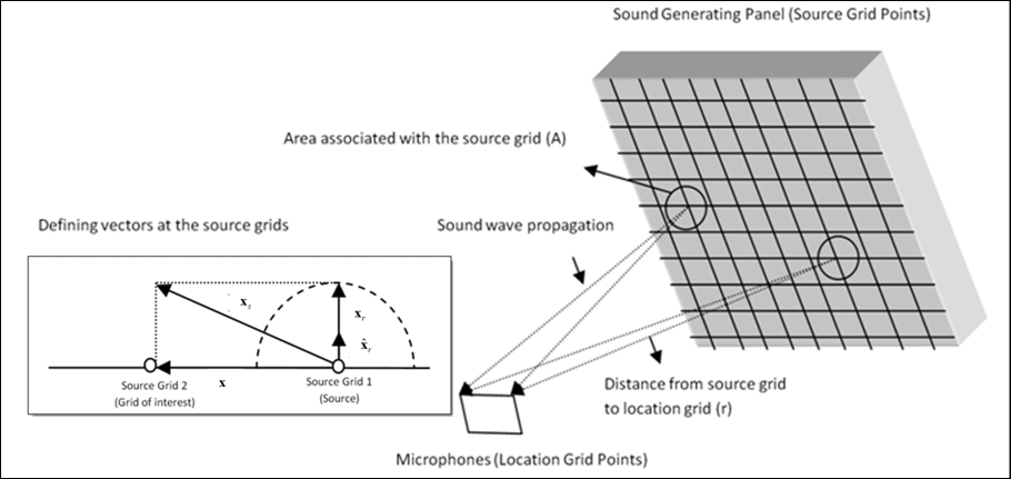
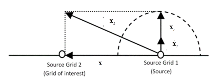
is the distance from the acoustic source grid j on the panel to the microphone location grid (Figure 1).

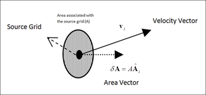
is the velocity flux of the source grid.

k is the wave number as defined in Wave Number.

i is the square root of -1

np is the number of source grids (Figure 1).

q is the value of the scale factor specified using the parameter PARAM, SPLFAC.

The Sound Pressure Level in decibels (SPLdB - also requested using SPL) can be calculated using the following equation:

Where, SPLdB is the Sound Pressure Level in decibels, is the magnitude of the acoustic sound pressure, and SPLREFDB is the reference sound pressure value specified using the parameter PARAM, SPLREFDB.

hmtoggle_plus1Complex Particle Velocity Vector

The complex particle velocity vector is the velocity of a particle in a medium measured as a wave passes through it. The particle velocity is not the velocity of the wave itself; rather it is the velocity of a particle as it oscillates about a mean position, due to the passage of the wave. It is specified by at the location of the microphone, due to the source grid j (Figure 1) and is defined for each frequency as follows:

Where,

is the complex acoustic pressure, due to source grid, j at the microphone location.

is the unit vector from the source grid j to the microphone grid (Figure 1).

is the density of the acoustic medium defined by PARAM, SPLRHO.

c is the speed of sound defined by PARAM, SPLC.

k is the wave number as defined in Wave Number.

rj is the distance from the acoustic source grid j on the panel to the microphone grid (Figure 1).

i is the square root of -1

hmtoggle_plus1Total Sound Power (Requested using SPOWER)

The total sound power is the rate of change of sound energy with time in the domain of reference. The total sound power spf, due to all the source grids can be calculated at a microphone location for each frequency as follows:

Where, is the acoustic pressure at a microphone location, due to the source grid "j", is the complex conjugate of , and np is the number of source grids (Figure 1).

hmtoggle_plus1Total Complex Intensity Vector (Requested using SINTENS)

The total complex intensity vector is the sound power per unit area. The sound intensity can be defined as a product of sound pressure and the particle velocity vector. For multiple source grids, the total sound intensity at a microphone location for each frequency is given as follows:

Where, is the acoustic pressure at the microphone location due to the sound generated at the source grid "j" and is the complex conjugate of , which is the complex particle velocity vector at the microphone location, due to the sound generated at the source grid "j".

At the Source Grid Location

hmtoggle_plus1Wave Number

The wave number is independent of the location of the grid points. Now define a set of displacement vectors that relate source grids to one another. To do this, each source grid is considered to be associated with an area (A) on the panel.

radiated_sound_disp_vectors

Figure 3: Displacement vectors at the source grids.

The vector addition operation for displacement vectors from Figure 3 is as follows:

Where,

is the vector from a source grid (1) to the source grid (2) of interest.

is defined as:

Where, A is the area associated with a source grid and is the unit normal to the area, A associated with a source grid.

hmtoggle_plus1Complex Acoustic Sound Pressure [at the source grid]

The complex acoustic sound pressure is the deviation from the ambient atmospheric pressure caused by a sound wave. This is specified using and is defined at the source grid for each frequency as follows:

Total Complex Acoustic Sound Pressure at a source grid requested by SPL is:

Where,

is the frequency of the sound wave in the medium.

is the density of the acoustic medium defined by PARAM, SPLRHO.

is equal to , for each grid, j (j=1 to np), as defined in At the Source Grid Location (Figure 3).

is the velocity flux of the source grid, j (Velocity Flux of the Source Grid)

k is the wave number as defined in Wave Number.

i is the square root of -1

np is the number of source grids (Figure 1).

q is the value of the scale factor specified using the parameter PARAM, SPLFAC.

hmtoggle_plus1Total Sound Power (Requested using SPOWER) [at the source grid]

The total sound power is the rate of change of sound energy with time in the domain of reference. The total sound power , due to all the source grids can be calculated at a source grid of interest for each frequency as follows:

Where,

is the acoustic pressure at a source grid, due to the source grid "j".

is the complex conjugate of .

np is the number of source grids (Figure 1).

hmtoggle_plus1Total Complex Intensity Vector (Requested using SINTENS) [at the source grid]

The total complex intensity vector is the sound power per unit area. The sound intensity can be defined as a product of sound pressure and the normal velocity vector. For multiple source grids, the sound intensity for each frequency is given as follows:

Where,

is the acoustic pressure at the source grid location of interest, due to the sound generated at the source grid "j".

is the complex conjugate of the normal velocity vector of the source grid of interest.

Where the normal velocity vector of the source grid of interest is given as:

Refer to at the source grid location and velocity flux of the source grid sections for a description of the terms.

See Also:

RADSND (Bulk Data)

RADSND (Subcase)