Spring Type 13 – Beam Type (/PROP/SPR_BEAM)
Spring type 13 functions like a beam element with six independent modes of deformation:
Contrary to a beam element, relations between displacements (resp. rotations) and forces (resp. moments) are not deducted from the geometry (area, length, and moment of inertia) and the material properties (Young modulus, shear modulus). Instead, they are user-defined through different stiffness formulations (see Stiffness for more details).
Spring type 13 works only if the length is not equal to zero. Nodes 1 and 2 are always used to define the local X-axis. Local Y direction is defined at time t=0 and its position is updated at each cycle, taking into account the mean X rotation. Initially, the Y-axis can be defined in different ways. A third node can be used for beam elements. It is also possible to use the local Y-axis of a skew frame. If a skew frame and third node are not defined, global Y-axis replaces the Y skew axis. If the Y skew axis is co-linear with the local X-axis, the local Y-axis and Z-axis are put in an arbitrary position. The Z-axis is finally computed as the cross product of X-axis and Y-axis.
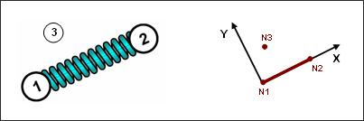
Fig. 3.9: Spring type 13
An illustration of a beam type spring is shown below (Fig. 3.10).
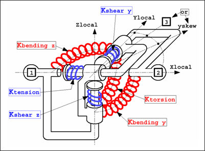
Fig. 3.10: Spring type 13
A bending deformation is illustrated in Fig. 3.11. This deformation only takes into account the difference of the two nodes rotations. Beam double bending does generate bending deformation; but shear deformation is shown below.
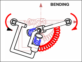
Fig. 3.11: Spring type 13 under bending
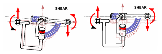
Fig. 3.12: Spring type 13 under shear-bending
The beam type spring behaves as a physical beam, in which the variation of bending moment in length generates the increase in shear. The shear force in the spring implies the change of bending moment.
| Note: | When defining the spring properties, it is strongly recommended to introduce values with physical meanings. A spring with high shear stiffness and a zero bending stiffness is not recommended and may lead to incorrect results. |
|
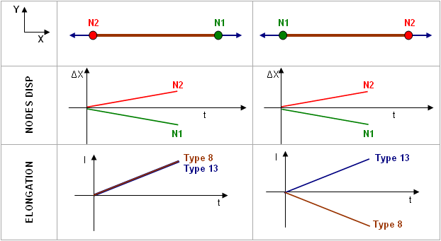
Contrary to spring type 8, rigid body rotation is possible without any artificial force and moment generation for spring type 13. Behaviors of spring type 8 and 13 under a rigid body rotation are compared in Fig. 3.13.
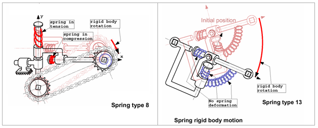
Fig. 3.13: Rigid body motions for springs type 8 and 13
To compute the critical time step, the same formula as spring type 4 is applied; the minimum overall degree of freedom is finally kept. Therefore to take into account the coupling between bending and shear, and the stiffness' in bending are modified:
Between spring type 8 and 13, the sign conventions is not the same, therefore results may be rather confusing when trying to compare both spring. For spring type 13, the deformation sign is based on the variation of initial length.
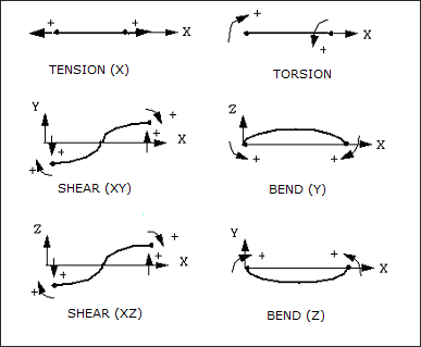
Fig. 3.14: Spring type 13 sign conventions
For a spring subjected to axial tension, the deformation will always be positive (Fig. 3.14). This is not true any longer for spring type 8, since this spring can have a zero length for one (or all) direction, positive and negative spring deformations cannot be defined with the variation of initial length. The sign convention chosen for all degrees of freedom is that a deformation is positive (resp. negative), if displacement (or rotation) of node 2 minus displacement (or rotation) of node 1 is positive (resp. negative).
The following example illustrates the difference between spring types 8 and 13, resulting from the sign conventions in RADIOSS.
For further information, refer to the RADIOSS Theory Manual.


